28
Rev. 2.0
07/27/2023
MBDV Hardware Manual
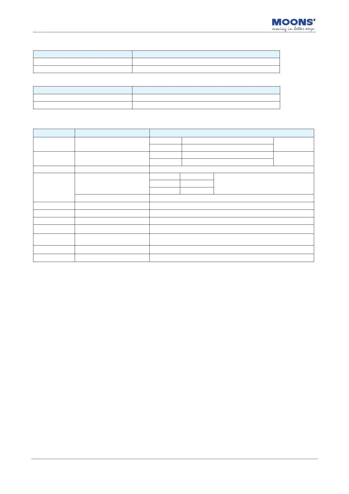
Baud rate:
SW7 Function Description
0 The baud rate is set by Luna software, the default is 1Mbps
1 500kpbs
Select the terminal matching resistor:
SW8 Function Description
0 No resistor connector between CAN_H and CAN_L
1 Connect a 120
Ω
resistor between CAN_H and CAN_L
4.2.3 Driver terminal description
Type Name Description
Main V+
、
V-
V+ positive terminal of Main power supply
V- negative terminal of Main power supply
AUX 24V
、
GND
24V Positive terminal of logic power supply
Can be
disconnected
GND negative terminal of logic power supply
REG REG Regenerative resistor connector
Motor
U
、
V
、
W
U Red
Three-phase power supply for the motorV Yellow
W Blue
Brake Motor brake connector
Encoder Encoder signal input interface Motor encoder connector
I/O I/O connection Input and output signal connector
Encoder Output Encoder signal output interface Encoder signal output connector
STO STO interface Safe torque o function connector
Wireless
Wireless debugging module
interface
Wireless debugging module connection port
USB USB debugging interface Connect to PC
COM1 / COM2 CAN open / RS-485 interface CAN open / RS-485 communication interface
4.2.4 Considerations when Wiring
• Please make sure that the driver and motor are well grounded, and the best grounding wire is
AWG10 above cables.
• The ground must be a single point ground.
• Check whether the V+ and V- connections are correct and the correct voltage is connected.
• If using an auxiliary power supply, connect the positive connector of the 24V power supply to
24V and the negative connector of the power supply to GND.
• Make sure the order of U, V, W is red, yellow, blue, wrong order will cause the motor to not
rotate or rotate randomly.
• An emergency stop circuit must be provided to ensure that the power can be cut o
immediately in the event of a fault.
• There is a large-capacity capacitor in the servo drive, even after the power is o, the high
voltage will still be maintained. 5 Do not touch the exposed parts of the drive and motor
terminals for a few minutes.
• Do not use the same sleeve for the main power cable and the input/output signal / encoder
cable, and do not bundle them together. When wiring, the main power cable and the input/
output signal cable / encoder cable should be separated by at least 30cm. Getting too close will
result in malfunction.
• Use twisted-pair or multi-core twisted-pair shielded cables for input/output signal cables and
encoder cables.
• The maximum wiring length of the input/output signal cable is 3m, and the maximum wiring
length of the encoder cable is 5m.