47
Rev. 2.0
07/27/2023
MBDV Hardware Manual
4.10.3 Input and Output Pinout
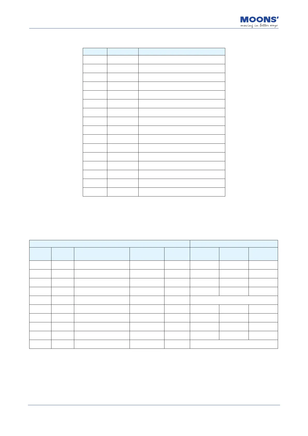
Pin NO. Signal Description
1 1_X1 Axis1_input 1
2 1_X2 Axis1_input 2
3 1_X3 Axis1_input 3
4 1_X4 Axis1_input 4
5 1_XCOM Axis1_input COM
6 1_YCOM Axis1_output COM
7 1_Y1 Axis1_output 1
8 1_Y2 Axis1_output 2
9 2_X1 Axis2_input 1
10 2_X2 Axis2_input 2
11 2_X3 Axis2_input 3
12 2_X4 Axis2_input 4
13 2_XCOM Axis2_input COM
14 2_YCOM Axis2_output COM
15 2_Y1 Axis2_output 1
16 2_Y2 Axis2_output 2
4.10.3.1 Digital Inputs
The MBDV-2X-520AC low voltage servo driver has 4 digital input signals for each axis. Each digital
input signal can be congured to have a special xed function. If a xed function is assigned to an
input, you may also congure the logic of the input.
Signal Factory default
I/O-pin
number
Signal
name
Signal description
Corresponding
parameters
Instruction Signal name
Input logic
*1
Defaults
1 1_X1 Axis1_input 1 P5-00 MU1 GPIN Closed 0
2 1_X2 Axis1_input 2 P5-01 MU2 GPIN Closed 0
3 1_X3 Axis1_input 3 P5-02 MU3 GPIN Closed 0
4 1_X4 Axis1_input 4 P5-03 MU4 E-STOP Closed 13
5 1_XCOM Axis1_input COM
—— ——
X1, X2, X3, X4 input common terminal
9 2_X1 Axis2_input 1 P5-00 MU1 GPIN Closed 0
10 2_X2 Axis2_input 2 P5-01 MU2 GPIN Closed 0
11 2_X3 Axis2_input 3 P5-02 MU3 GPIN Closed 0
12 2_X4 Axis2_input 4 P5-03 MU4 E-STOP Closed 13
13 2_XCOM Axis2_input COM
—— ——
X1, X2, X3, X4 input common terminal
Note:
*1. The level logic of the pin input is as follows:
Closed: The driver digital input circuit forms a loop, and current ows in or out of the input pins.
Open: The driver digital input circuit does not form a loop, and no current ows into or out of the input pins.
2. For details, please see: 7.1.1 Input signal setting