41
Rev. 2.0
07/27/2023
MBDV Hardware Manual
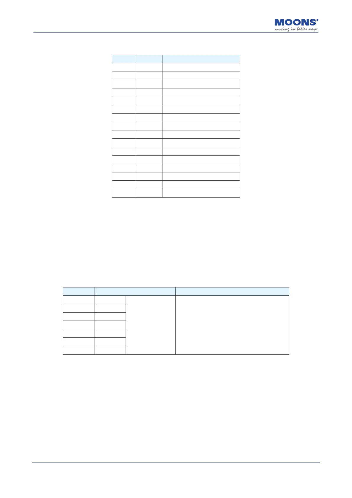
4.9.3 Input and Output Pinout
Pin NO. Signal Description
1 AOUT+ Encoder output A+
2 AOUT- Encoder output A-
3 BOUT+ Encoder output B+
4 BOUT- Encoder output B-
5 ZOUT+ Encoder output Z+
6 ZOUT- Encoder output Z-
7 DGND Digital ground
8 DGND Digital ground
9 X1 Digital input 1
10 X2 Digital input 2
11 X3 Digital input 3
12 X4 Digital input 4
13 XCOM Digital input common terminal
14 YCOM Digital output common terminal
15 Y1 Digital output 1
16 Y2 Digital output 2
Note: MBDV-520AC does not support encoder frequency division output function, if you need this
function, please select MBDV-520AC-H01.
4.9.3.1 Encoder Feedback Output
The MBDV-520AC can output A/B/Z phase signals via line driver, dierential outputs with a
maximum of 5 V.
The host computer must use a dierential line receiver to be able to accept the signals from the
drive. We recommend that a twisted pair, shielded wire be used for the transmission of encoder
feedback signals.
I/O - pin NO. Signal name Description
1 AOUT+
Encoder Feedback
Outputs
The encoder feedback is output in the form of
A/B/Z dierential signals. A/B/Z output signals
and the frequency division ratio that aects the
output frequency of the encoder feedback can
be congured via parameters.
2 AOUT-
3 BOUT+
4 BOUT-
5 ZOUT+
6 ZOUT-
7,8 DGND