131
Rev. 2.0
07/27/2023
MBDV Hardware Manual
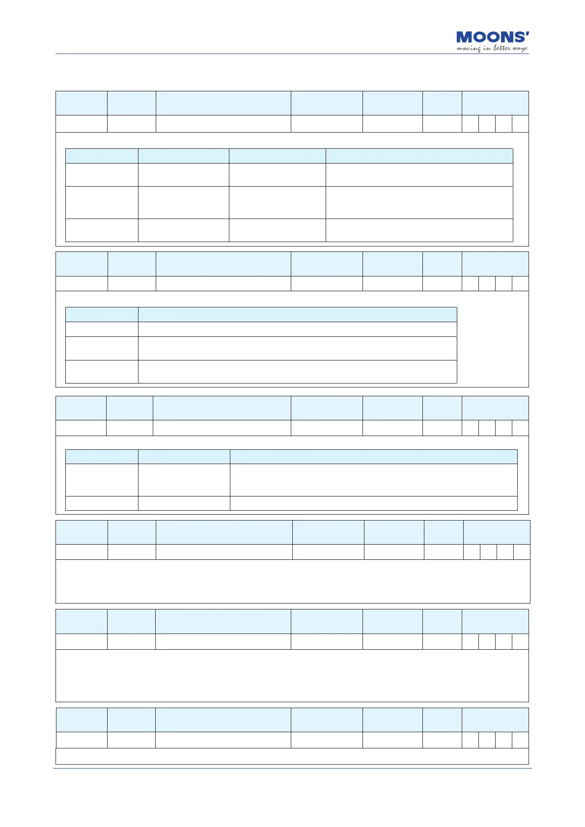
8.3.2 Group P1-XX: Conguration --- Conguration class parameters
Parameter Instruction Name Defaults Range Unit
Related
Patterns
P1-00 CM Control mode 21 1,15,21 - P S T
Parameter P1-00 can be used to set the main control mode of the drive.
Set value Mode Control signal Description
1 Torque Control
Communication
command
Use communication commands to control motor
output torque
15 Velocity Control Digital input signal
Internal 8 speed mode with parameters P2-10~P2-
17setting speed values for each of the 1-8 speed
settings, respectively.
21 Position Control
Communication
command
Point-to-point position mode control using
communication instructions
Parameter Instruction Name Defaults Range Unit
Related
Patterns
P1-02 PM Control Mode on power up 10 8 ~ 10 - P S T
Parameter P1-02 can be used to set the communication mode and working status of the drive after power-on.
Set value Mode
8 Power-on running in Modbus/RTU mode, servo automatically enabled upon power-on
9
Running in Q mode that supports Modbus/RTU communication, the servo automatically
enables and automatically executes the Q program when powered on.
10
Power-on running in Q mode that supports Modbus/RTU communication, servo is not
enabled automatically after power-on, Q program is not executed automatically
Parameter Instruction Name Defaults Range Unit
Related
Patterns
P1-03 JM Jog Mode 2 1 ~ 2 - P S T
When jogging the motor, users can congure the drive for pure velocity control or for velocity and position control.
Set value Mode Mode
1 Position over time
Position and velocity tracking are monitored for errors. If the motor incurs
a greater position error than dened by P3-04, the drive will fault out with a
position error fault.
2 Velocity control only Only velocity tracking is monitored for errors.
Parameter Instruction Name Defaults Range Unit
Related
Patterns
P1-05 GC Current command for Torque Control 0 -3000 ~ 3000 0.1% P S T
When the drive is operated in torque control (command based), this parameter denes the commanded current limit. The current draw
dictates the output torque of the motor so therefore, this limit denes the maximum output torque allowable from the motor. The motor
will stop motion when it reaches this current value and will try to maintain position.
Note:
This current value is not maintained after power cycles.
Parameter Instruction Name Defaults Range Unit
Related
Patterns
P1-06 CC 1st Torque Limit 3000 0 ~ 3000 0.1% P S T
Sets the maximum continuous current level for the servo motor when operating in Point-to-Point mode and Velocity Control Mode. It
sets the upper limit on the continuous current range the motor may draw. However, users must be aware that the motor can still draw
more than the set continuous current, therefore output higher torque, but they will be operating in what is known as the Peak Current
which is only allowed for a limited amount of time.
Behaves as the rst torque limit when operating in Torque Control.
Parameter Instruction Name Defaults Range Unit
Related
Patterns
P1-07 CV Target Torque 0 0 ~ 3000 0.1% P S T
Torque arrival signal judgment value. Please refer to chapter 7.4.9 Torque arrives