57
Rev. 2.0
07/27/2023
MBDV Hardware Manual
6 Commissioning
During trial operation, it is recommended that the motor be operated without a load coupled to its
shaft.
6.1 Inspection before commissioning
To protect the servo drive and servo motor, it is recommended that users inspect the following
before commissioning these two components.
1) Wiring
Check that Main power, AUX power (if used), motor phases and motor encoder are securely and
properly wired to the drive. Check that no short circuits exist between connections. Verify that
motor and drive are properly grounded . Ensure that the USB connection is secure to ensure
proper communication with the host PC.
2) Power supply voltage
Verify that the voltage applied to Main power is within the specication of the drive. Verify that the
voltage applied to AUX power is 24 VDC.
3) Make sure the motor and drive are securely mounted
4) Make sure the motor shaft is not loaded
6.2 Commissioning Steps
Step Content Description
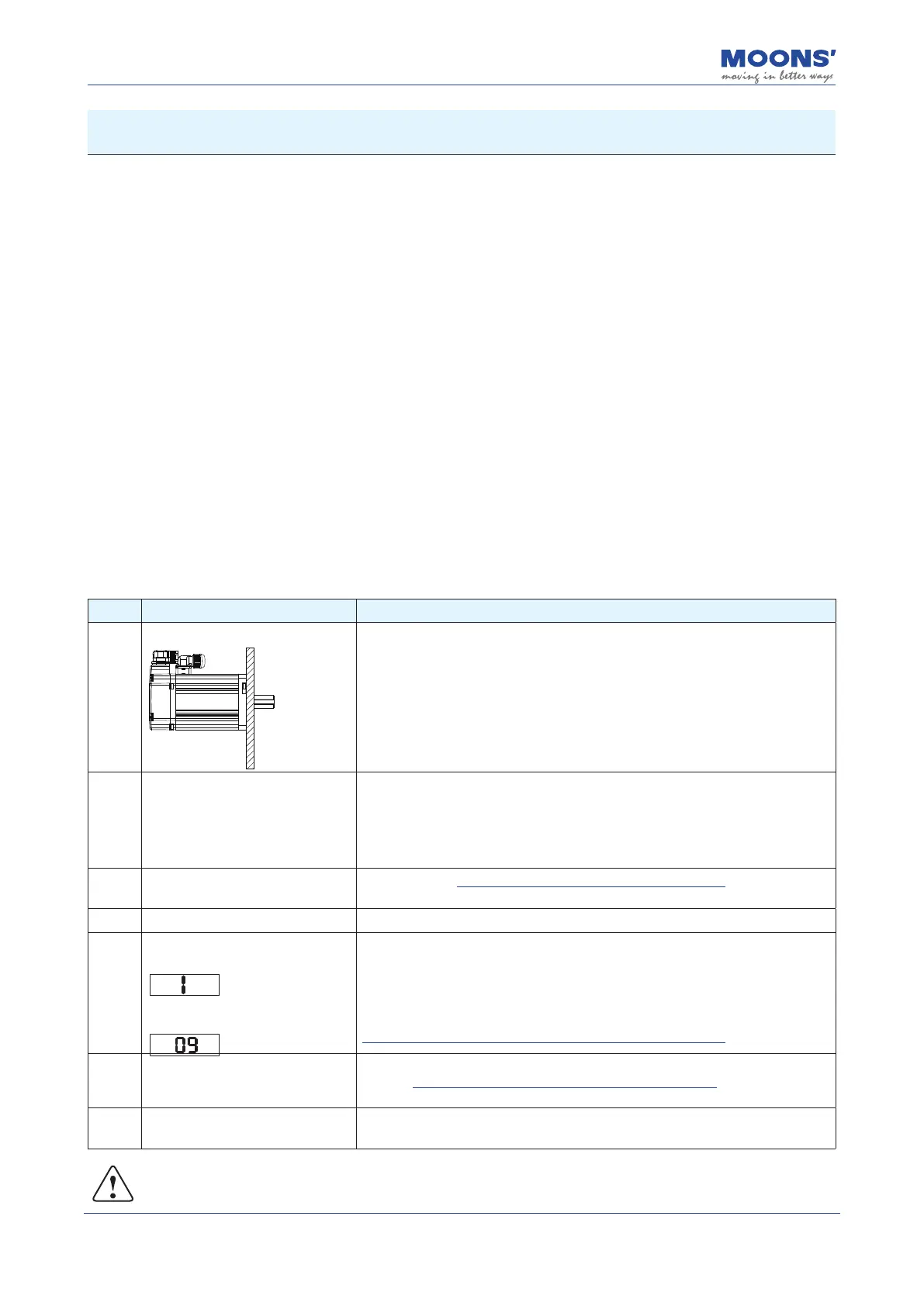
1
Securely mount the motor
1) Servo motor can be mounted on the machine
2) Please do not connect the load to the servo motor
2
Ensure proper and secure
connection between motor and
drive
1) MBDV Servo motor phases are labeled U, V, W for the red, yellow and blue
cables respectively. If using a third party motor, this wiring could be dierent and
its performance is not guaranteed with the MBDV.
2) Ensure that the motor encoder cable is properly connected to the encoder
port on the MBDV drive.
3
Make sure the power circuit wiring
is correct
Refer to chapter 4.3 Wiring of External Main Circuit to conrm whether the
power input circuit is correct
4 Power on Input 24 ~60VDC power supply
5
During normal operation, the drive
displays its Node ID
If an alarm occurs, it will display
the alarm code in blinking fashion
1) Normally, the drive has no alarm display and is disabled
2) If r09 alarm occurs, it indicates that there is a problem with the cable
connection of the encoder. Please check whether the wiring is correct after
power o.
3) For other alarms, please refer to Chapter 9 Troubleshooting
6
If a motor brake is used, the brake
control circuit should be set up
before use.
Refer to 4.6 Connection of Motor with Electromagnetic Brake
7 JOG mode operation
If there is no abnormality in the above steps, you can start a trial operation in
JOG mode
Note: The drive must be congured for the proper motor model. Please refer to the following
steps before initiating motion with the motor.