31
Rev. 2.0
07/27/2023
MBDV Hardware Manual
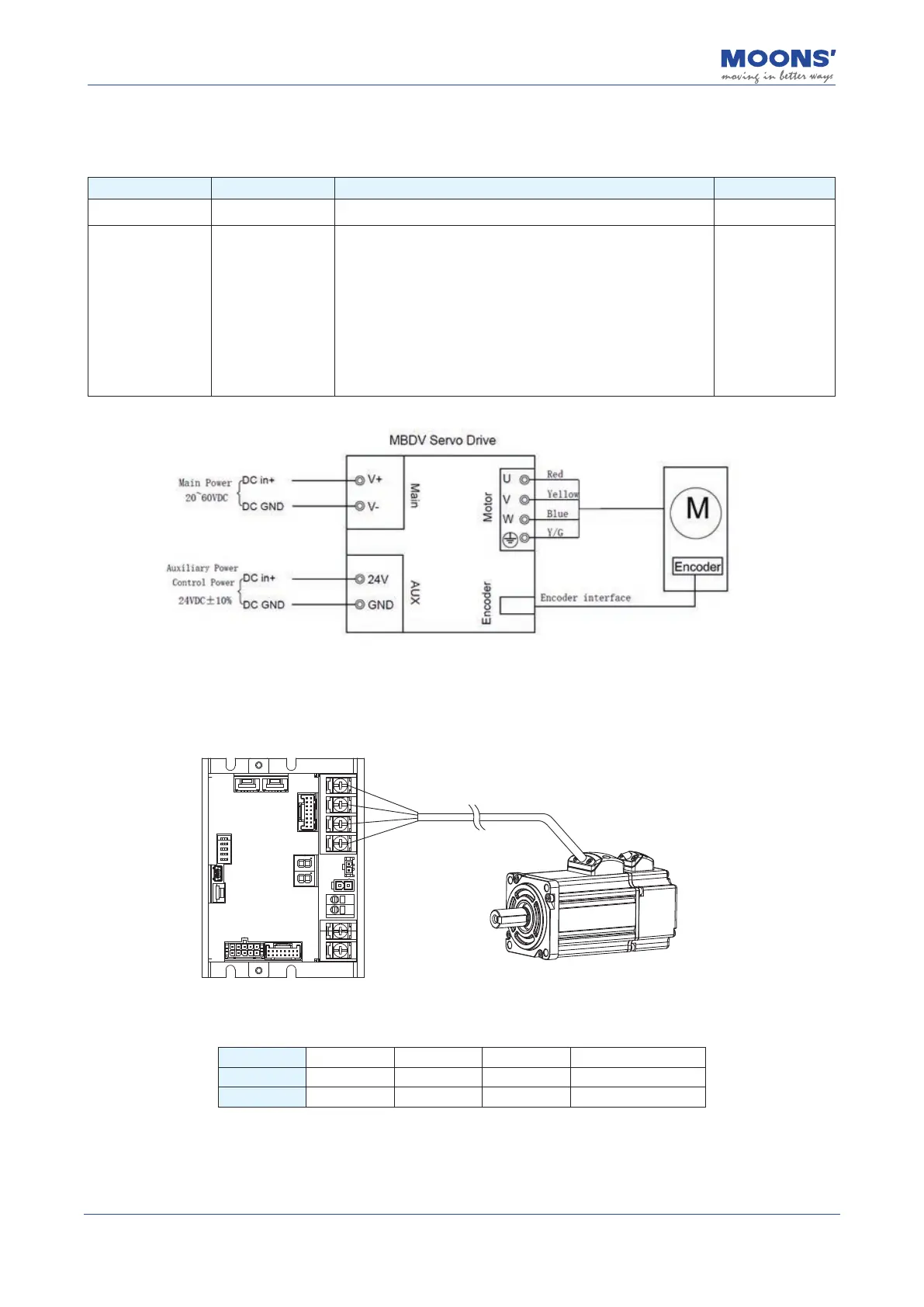
4.3 Main & AUX - Driver power wiring method
MBDV series DC servo has two power supplies.
Pin Function Input specication
Main power V+, V- Drive main power input 24 ~ 60VDC
Auxiliary Power /
Control Power
24V, GND
In the event of a mains power failure, the following two
applications require auxiliary power to be turned on:
a) When the DSP part of the driver is required to work
normally
b) Use the dedicated brake output port on the driver to
directly drive the brake of the motor
When the main circuit resumes power supply, the upper
computer controller can quickly restore the position control.
24VDC
±
10%
4.4 Motor connection method
4.4.1 Block diagram of the connection between the driver and the motor power line
U
V
W
PE
4.4.2 Denition of motor power line wiring
Signal U V W PE
Name U phase V phase W phase Motor ground wire
Color Red Yellow Blue Yellow /Blue