55
Rev. 2.0
07/27/2023
MBDV Hardware Manual
5 LED Display
5.1 Display content
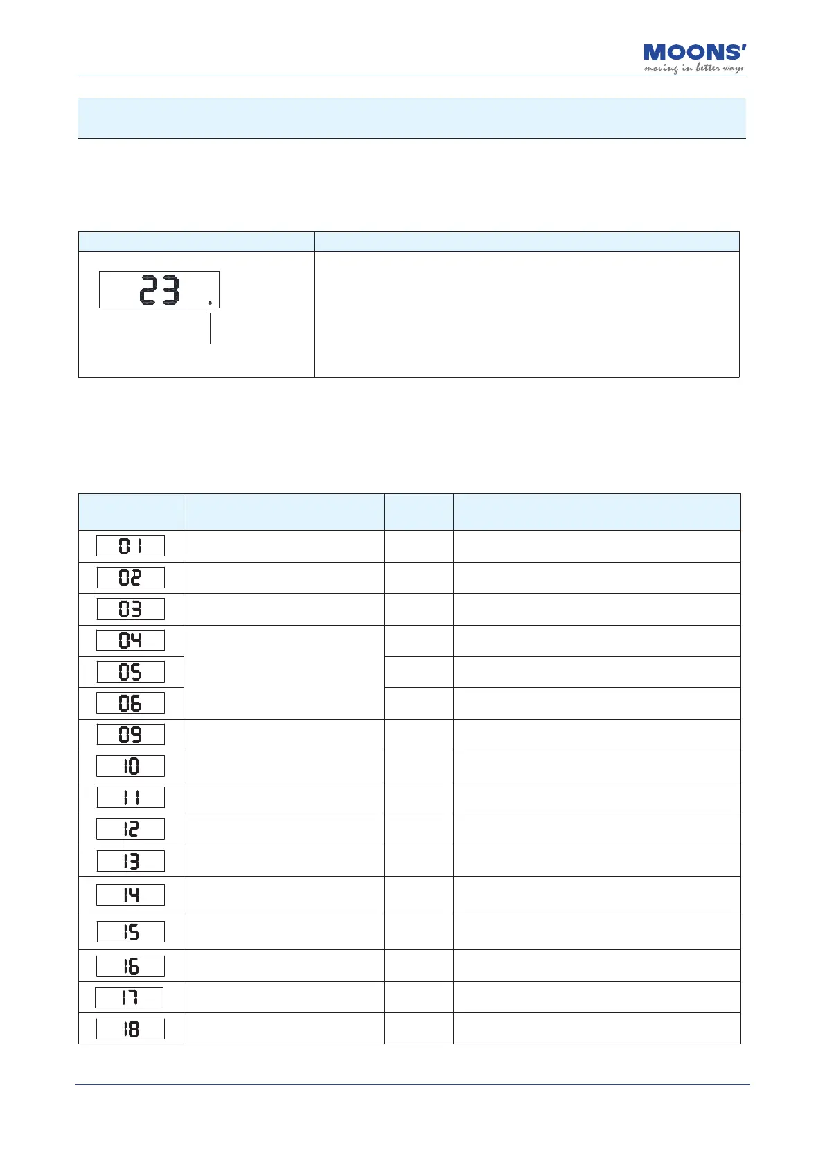
5.1.1 Decimal point meaning
Display content Description
Enable identification bit
◆
Motor Enabled Flag: The decimal point in the lower right corner of the
LED panel is the identication bit alerting users to the servo motor's status
Solid: Motor enabled
Blank: Motor is disabled
5.2 Alarm Codes and Denitions
When the MBDV drive experiences abnormal operation, it will enter an alarm state and display one
of the following codes. Their denitions are included below for reference.
Alarm Code Description
Alarm
Type
Drive status after alarm
Drive over temperature Fault Servo o
Internal voltage Fault Servo o
Drive overvoltage Fault Servo o
Overcurrent
Fault Servo o
Fault Servo o
Fault Servo o
Encoder feedback error Fault Servo o
Position following error Fault Servo o
Low voltage Fault Servo o
Over speed Fault Servo o
Limit switch triggered Warning Does not change the current state
Positive limit switch triggered Warning
Does not change the current state, the motor cannot
rotate negatively.
Positive limit switch triggered Warning
Does not change the current state, the motor cannot
rotate positively.
Current limit Warning Does not change the current state
Communication error Warning Does not change the current state
Parameter save failed Warning Does not change the current state