62
Rev. 2.0
07/27/2023
MBDV Hardware Manual
7.1.5 CW, CCW Limit
In order to prevent the movable parts of the machine from exceeding the movable range and avoid
accidents, it is necessary to set CW and CCW limit switches.
◆
Signal logic
Type Signal name Setting Signal logic Function
Input
CCW-LMT
7 Closed
When the input state is CLOSED, the drive shows a Negative Limit alarm,
motor cannot continue rotating in negative direction.
8 Open
When the input state is OPEN, the drive shows a Negative Limit alarm,
motor cannot continue rotating in negative direction.
CW-LMT
5 Closed
When the input state is CLOSED, the drive shows a Positive Limit alarm,
motor cannot continue rotating in positive direction.
6 Open
When the input state is OPEN, the drive shows a Positive Limit alarm,
motor cannot continue rotating in positive direction.
◆
Default settings for MBDV series drives
Signal
name
Input PIN NO. Parameter Command
Setup
value
Function
Support
mode
CCW-LMT
X1 9
P5-00 MU1 7
Motor CW limit signal input
P V T
XCOM 13
CW-LMT
X2 10
P5-01 MU2 5
Motor CCW limit signal input
XCOM 13
7.1.6 Gain Select
Use the Gain Select function to meet performance requirements of varying loads. There are
dierent methods of using the Gain Select function. One of these is through an digital input.
Another is called automatic gain switching. These are explained in this section.
1) Increasing the gain can decrease and suppress vibration when doing position control.
2) Reducing the gain can decrease the settling time when the motor comes to a stop.
3) When the motor is running, increasing the gain can improve command following performance.
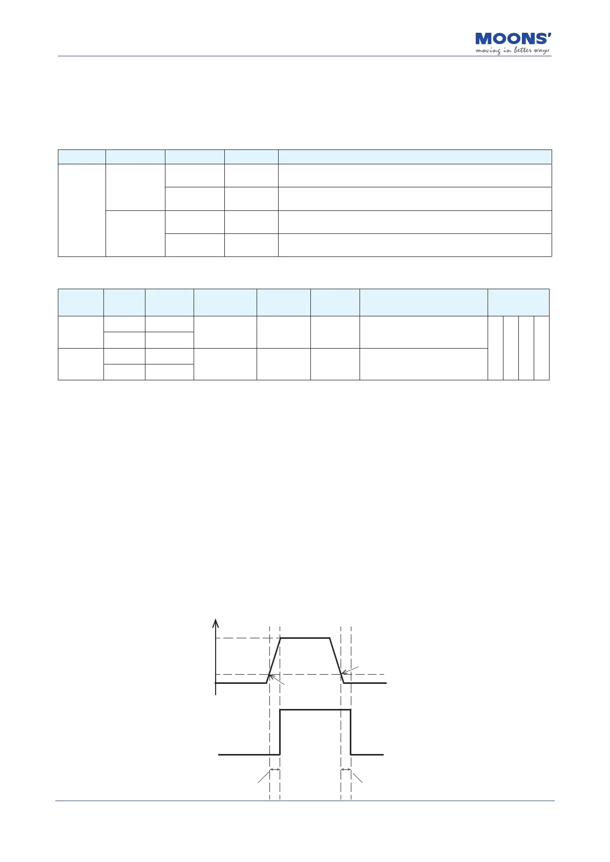
Example:
When the motor is running at low speed or stopped, a lower gain can be used to reduce noise,
but when the motor is running at high speed or positioning, switch to a higher gain to improve
command following performance.
Motor Speed
Gain Select
Gain Group 1
Lower gain
Gain Group 1
Lower gain
Gain Group 2
Higher gain
Speed higher than
P0-35
Switch delay time from
Group 1 to Group2
Switch delay time from
Group 2 to Group1
0
1500
P0-35
Speed lower than
P0-35
 Loading...


