51
Rev. 2.0
07/27/2023
MBDV Hardware Manual
◆
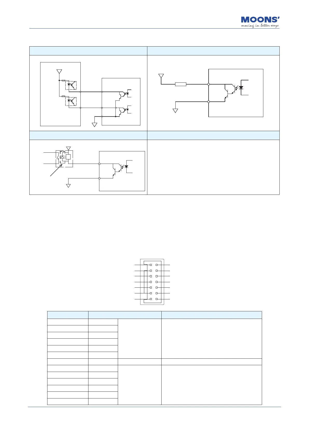
Connection examples
A. Connected to the control's optocoupler B. Connected to resistor load
16
Y2
15
Y1
YCOM
14
24VDC
Master/Controller
Servo Drive
Y1 / Y2
0VDC
YCOM
24VDC
Servo Drive
C.Connected to inductive load(Relay.etc.)
Y1 / Y2
0VDC
YCOM
24VDC
Relay
Servo Drive
1. Be sure to install the
freewheeling diode,
Otherwise, the output port will
be damaged
2. Pay attention to the
freewheeling diode polarity
4.10.4 Encoder Feedback Output
The MBDV-2X-520AC can output A/B/Z phase signals via line driver, dierential outputs with a
maximum of 5 V. The driver is able to output encoder feedback for each axis.
The host computer must use a dierential line receiver to be able to accept the signals from the
drive. We recommend that a twisted pair, shielded wire be used for the transmission of encoder
feedback signals.
1_AOUT-
1_BOUT-
1_ZOUT-
DGND
2_AOUT-
2_BOUT-
2_ZOUT-
1_AOUT+
1_BOUT+
1_ZOUT+
DGND
2_AOUT+
2_BOUT+
2_ZOUT+
1
3
5
7
9
11
13
2
4
6
8
10
12
14
Encoder - Pin NO. Signal name Description
1 1_AOUT+
Axis 1 Encoder
Feedback Outputs
The encoder feedback is output in the form of
A/B/Z dierential signals. The number of pulses per
revolution can be congured via the Pulse Output
Gear Ratio.
2 1_AOUT-
3 1_BOUT+
4 1_BOUT-
5 1_ZOUT+
6 1_ZOUT-
7,8 DGND Digitally
9 2_AOUT+
Axis 2 Encoder
Feedback Outputs
The encoder feedback is output in the form of
A/B/Z dierential signals. The number of pulses per
revolution can be congured via the Pulse Output
Gear Ratio.
10 2_AOUT-
11 2_BOUT+
12 2_BOUT-
13 2_ZOUT+
14 2_ZOUT-