45
Rev. 2.0
07/27/2023
MBDV Hardware Manual
◆
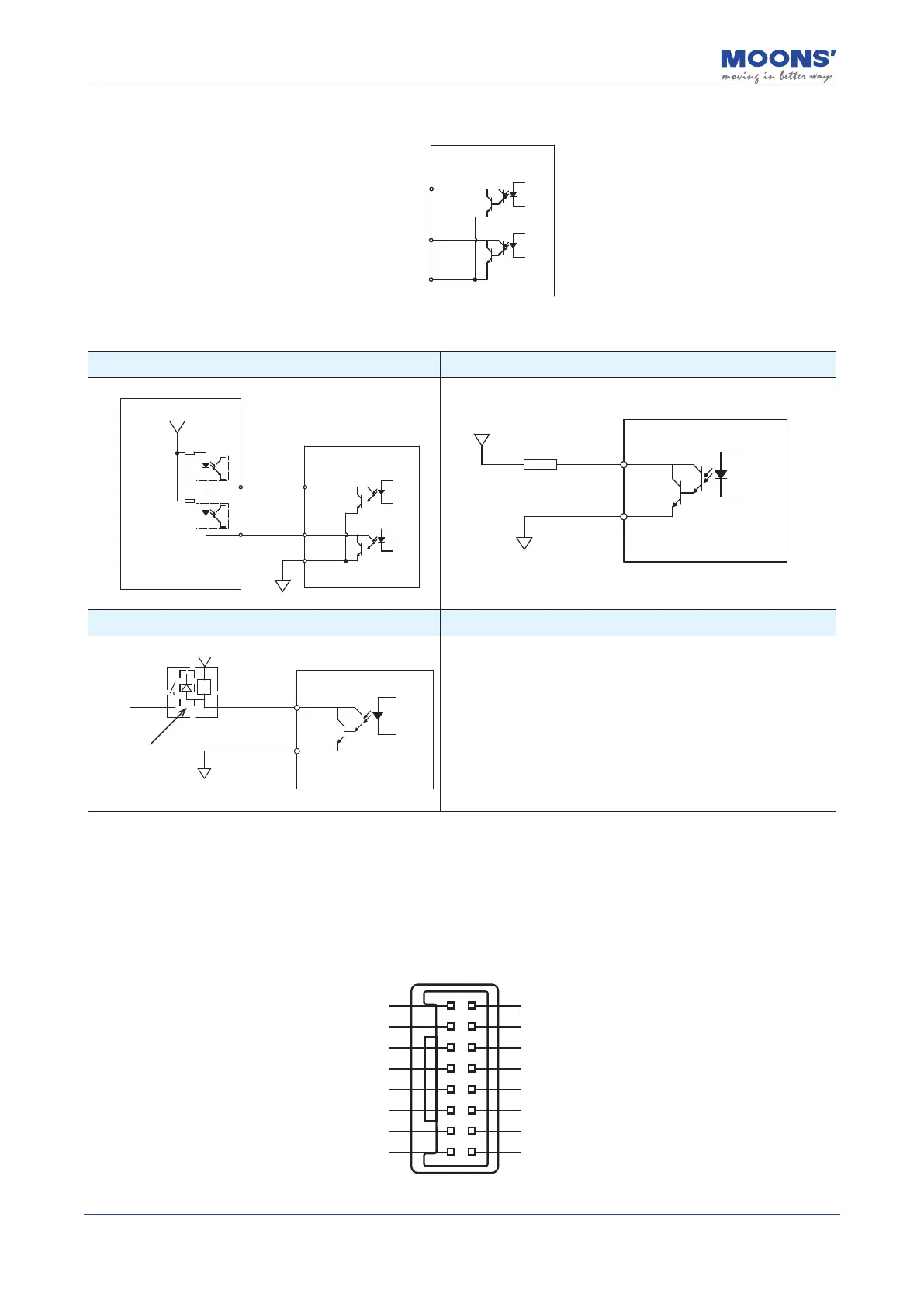
The internal circuit block diagram of Y1 ~ Y2 are as shown below.
16
Y2
15
Y1
YCOM
14
◆
Y1 ~ Y2 connection examples
A. Connected to the control's optocoupler B. Connected to resistor load
16
Y2
15
Y1
YCOM
14
24VDC
0VDC
Master/Controller
Servo Drive
Y1 / Y2
0VDC
YCOM
24VDC
Servo Drive
C.Connected to inductive load(Relay.etc.)
Y1 / Y2
0VDC
YCOM
24VDC
Relay
Servo Drive
1. Be sure to install the
freewheeling diode,
Otherwise, the output port will
be damaged
2. Pay attention to the
freewheeling diode polarity
4.10 Input and Output Signals (MBDV-2X-520AC)
4.10.1 Input and Output Specications
I/O port of MBDV-2X-520AC low-voltage servo driver is used to connect input and output signals.
The pin denitions are as follows:
1_X1
1_X3
1_XCOM
1_Y1
2_X1
2_X3
2_XCOM
2_Y1
1_X2
1_X4
1_YCOM
1_Y2
2_X2
2_X4
2_YCOM
2_Y2
1
3
5
7
9
11
13
15
2
4
6
8
10
12
14
16
The input and output signal specications are as follows: