125
Rev. 2.0
07/27/2023
MBDV Hardware Manual
8.3 Parameter Description
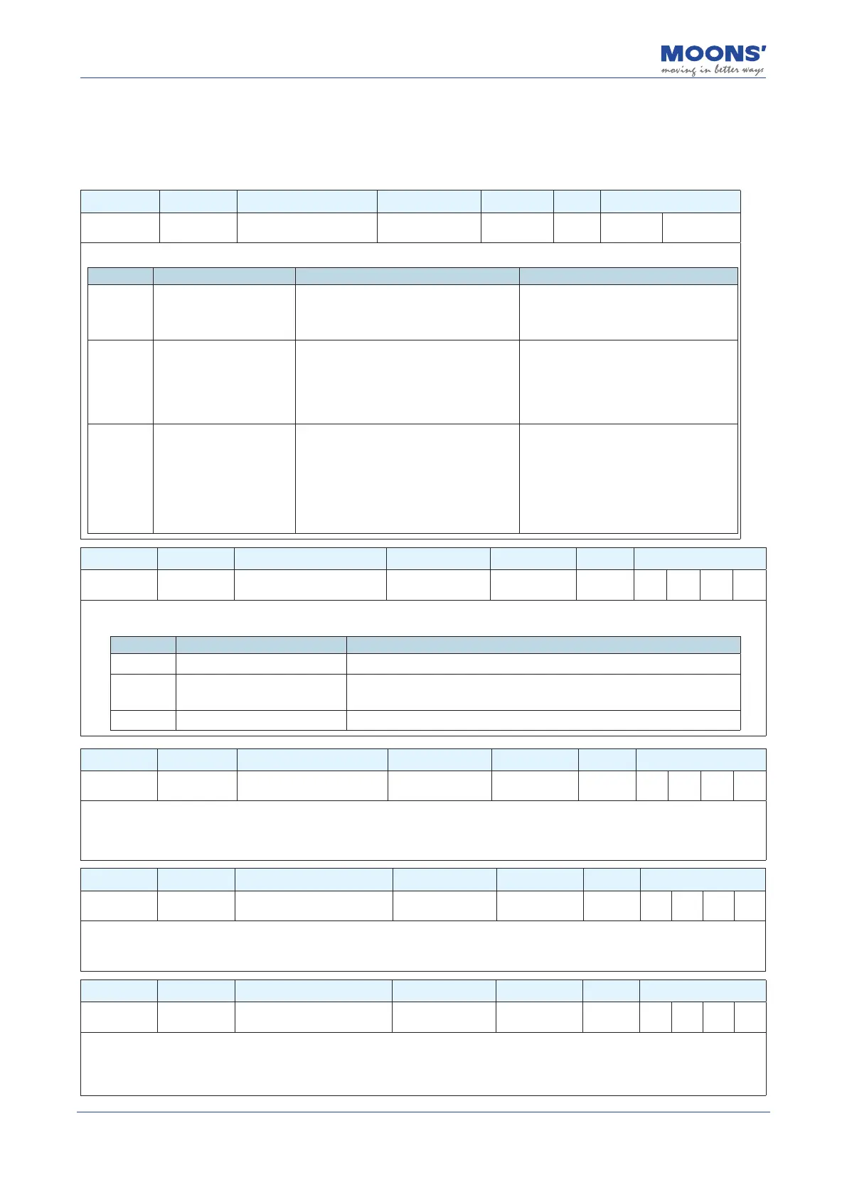
8.3.1 Group P0-XX: PID gain setting
Parameter Instruction Name Defaults Range Unit Related Patterns
P0-00 UM Tuning Mode 0 0 ~ 2 --- P S
Set the parameter tuning method.
Set value Parameter setting mode Description note
0 Tuning Free
Set the gain value of servo system by
setting P0-03.
In this mode, only modication of P0-03 is
valid.Manual adjustment of all other gain
and tuning parameters is not allowed.
1 Auto Tuning
Parameters are automatically set (load
inertia, mechanical stiness and gains).
Only the 1st Mechanical Stiness (P0-03)
and the Load Inertia Ratio (P0-02) can be
manually edited.
In this mode, only P0-03 stiness
level and P0-02 load inertia ratio are
valid. Manual adjustment of other gain
parameters is invalid.
2
Fine Tuning
Fine tuning allows users to manually
congure all gain, lter and load
characteristics for tuning. A recommended
method is to rst use auto-tuning to get
a close estimate of the required tuning
parameter values and then manually adjust
those estimates until a more accurate
tuning prole is reached.
In this mode, all gain parameters are
valid.
Parameter Instruction Name Defaults Range Unit Related Patterns
P0-01 LY Load type 0 0 ~ 10 --- P S T
Set the current load type. In auto-tuning mode and advanced tuning mode, setting the load type reasonably is conducive to accurate
identication and optimization of system gain parameters.
Set value Parameter setting mode Description
0 General load Ex: horizontally placed screw class load.
1 Rigid load Ex: rigid mechanism, such a horizontal installation like a turntable.
2 Flexible load Ex: Belt driven load
Parameter Instruction Name Defaults Range Unit Related Patterns
P0-02 NR Load inertia ratio 0 0 ~ 100 --- P S T
The current load inertia ratio. Set the ratio of load inertia to motor rotor inertia.
When auto-tuning is in progress, the load inertia ratio of the current system can be identied in real time, and this parameter will be
automatically saved after auto-tuning is completed. When the load inertia ratio is set correctly, P0-05 can accurately represent the
current system gain.
Parameter Instruction Name Defaults Range Unit Related Patterns
P0-03 KG 1st Mechanical Stiness Level 5 1 ~ 20 --- P S T
The rst stiness value of the current system.
When the parameter tuning mode P0-00 is set to free tuning and automatic tuning, the higher the mechanical Stiness level, the
stronger the gain of the servo system and the faster the response, An excessively large value will cause system vibrations.
Parameter Instruction Name Defaults Range Unit Related Patterns
P0-04 KX
2nd Mechanical Stiness
Level
5 1 ~ 20 --- P S T
The second stiness value of the current system. When the gain switch is turned on, the second stiness level will be eective under
the corresponding conditions. For details on gain switching, please refer to 7.1.6 Gain switching function.
When the parameter tuning mode P0-00 is set to free tuning and automatic tuning, the higher the mechanical Stiness level, the
stronger the gain of the servo system and the faster the response, An excessively large value will cause system vibrations.