40
Rev. 2.0
07/27/2023
MBDV Hardware Manual
4.9 I/O Input and output signal wiring (MBDV-520AC)
4.9.1 I/O Input and output signal specications
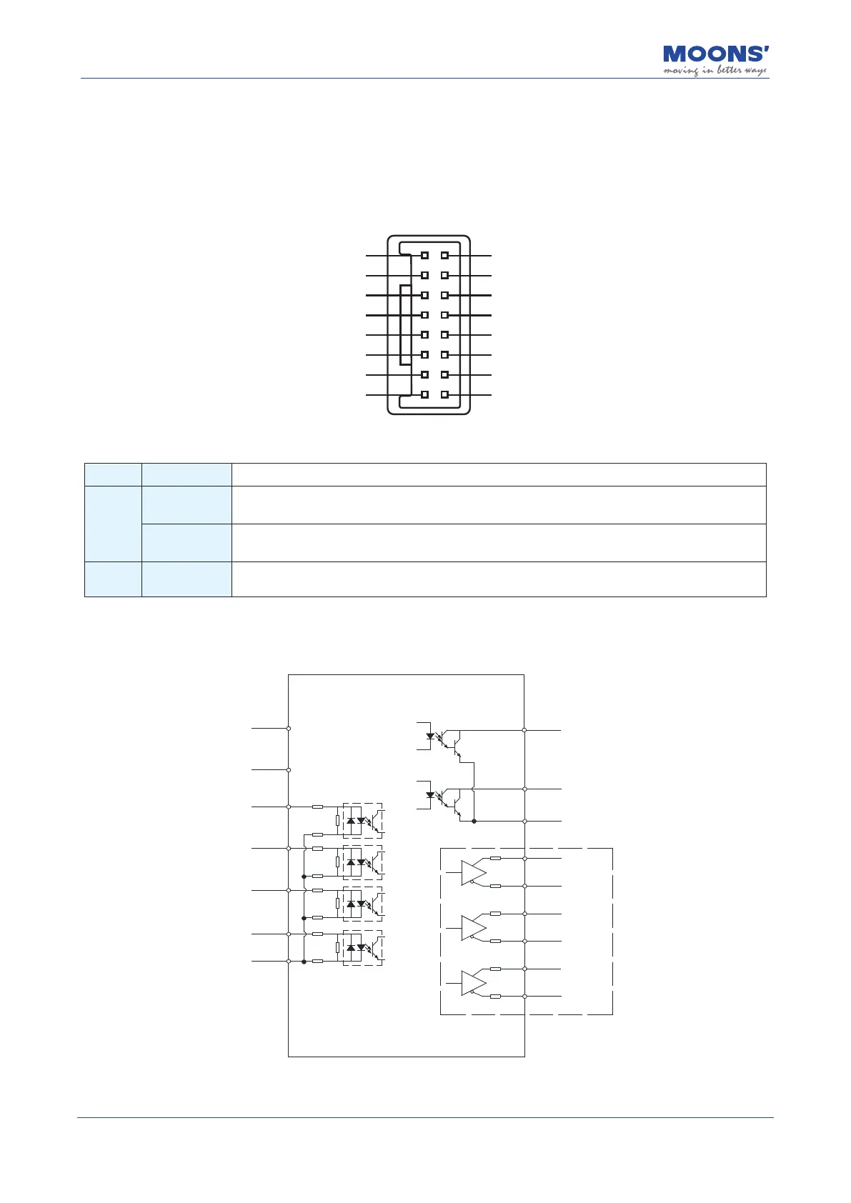
I/O port of MBDV-520AC low-voltage servo driver is used to connect input and output signals. The
pin denitions are as follows:
AOUT+
BOUT+
ZOUT+
GND
X1
X3
XCOM
Y1
AOUT-
BOUT-
ZOUT-
GND
X2
X4
YCOM
Y2
1
3
5
7
9
11
13
15
2
4
6
8
10
12
14
16
The input and output signal specications are as follows:
Classication
Description
Digital
Signals
Inputs
4 optically isolated inputs, can be congured by parameters, 24VDC, maximum current
20mA
Outputs
2 optically isolated outputs, can be congured by parameters, maximum 30 VDC, maximum
output current 30 mA
Pulse
Signals
Outputs
3 line driver outputs: Encoder A/B/Z signals
4.9.2 I/O Signal Pin Block Diagram
10Ω
10Ω
10Ω
10Ω
10Ω
10Ω
9
X1
10
X2
11
X3
12
X4
13
XCOM
2.4KΩ
2.4KΩ
2.4KΩ
2.4KΩ
2.4KΩ
2.4KΩ
2.4KΩ
2.4KΩ
AOUT+
AOUT-
BOUT+
BOUT-
ZOUT+
ZOUT-
1
2
3
4
5
6
16
Y2
15
Y1
YCOM
编码器
反馈输出
14
7
DGND
8
DGND