121
Rev. 2.0
07/27/2023
MBDV Hardware Manual
8 Parameter setting
8.1 Parameter classication
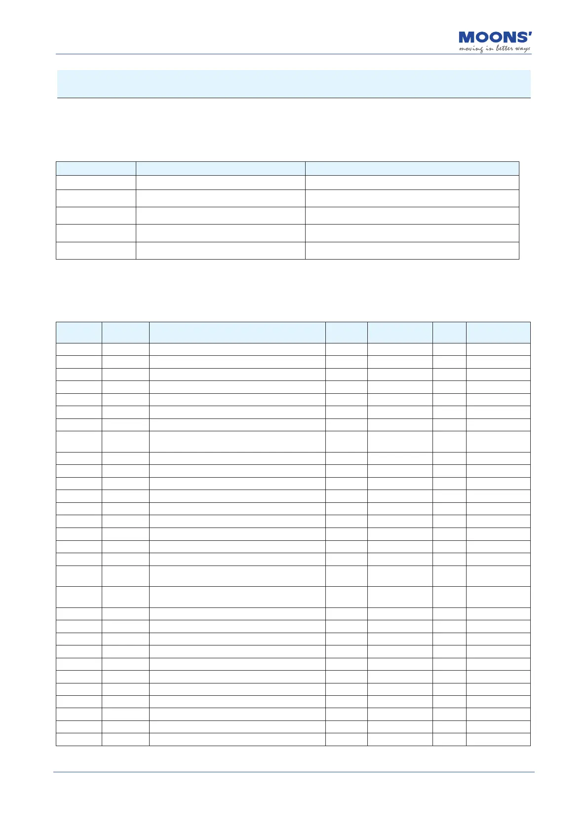
MBDV series low voltage servo has 5 groups of parameters.
Parameter group Type Function
P0-XX PID Tuning Set the gain parameters of the servo
P1-XX Drive Conguration
Congure functions and set various functional parameters
of the drive
P2-XX Motion Prole Conguration Congure motion prole parameters for each control mode.
P3-XX Encoder Settings
Congure parameters related to the encoder and encoder
output.
P5-XX Digital I/O Signal Settings
Congure the functions and parameters of digital inputs
and outputs.
8.2 List of parameters
P0-XX: PID Tuning
Serial
number
Command Function Defaults Range Unit Eective
P0-00 UM Tuning Mode 0 0 ~ 2
——
P0-01 LY Load type 0 0 ~ 10
——
P0-02 NR Load inertia ratio 0 0 ~ 100
——
P0-03 KG 1st mechanical stiness level 5 0 ~ 20
——
P0-04 KX 2nd mechanical stiness level 5 0 ~ 20
——
P0-05 KP 1st position loop gain 52 0 ~ 20000 0.1Hz
P0-07 KD 1st position loop derivative time constant 2000 0 ~ 30000 ms
P0-08 KE 1st position loop derivative lter 20000 0 ~ 40000 0.1Hz
P0-09 KL Velocity feedforward gain 10000 -30000 ~ 3000 0.01%
P0-10 KR Velocity feedforward lter frequency 20000 0 ~ 40000 0.1Hz
P0-11 KF 1st velocity command gain 10000 -30000 ~ 3000 0.01%
P0-12 VP 1st velocity loop gain 183 0 ~ 30000 0.1Hz
P0-13 VI 1st speed loop integral time constant 189 0 ~ 30000 ms
P0-14 KK Acceleration feed forward gain 3000 0 ~ 10000 0.01%
P0-15 KT Acceleration feedforward lter frequency 20000 0 ~ 40000 0.1Hz
P0-16 KC 1st command torque lter frequency 1099 0 ~ 40000 01Hz
P0-17 UP 2nd position loop gain 52 0 ~ 20000 0.1Hz
P0-19 UD 2nd position loop derivative time constant 2000 0 ~ 30000 ms
P0-20 UE 2nd position loop derivative time constant 15000 0 ~ 40000 0.1Hz
P0-21 UF 2nd velocity command gain 10000 -30000 ~ 3000 0.01%
P0-22 UV 2nd velocity loop gain 183 0 ~ 30000 0.1Hz
P0-23 UG 2nd velocity loop integral time constant 189 0 ~ 30000 ms
P0-24 UC 2nd command torque lter frequency 1099 0 ~ 40000 01Hz
P0-33 SD Automatic gain switching method 0 0 ~ 4
——
P0-34 PN
Gain switching condition - position error
0 0 ~ 2147483647 Pulses
P0-35 VN
Gain switching condition - actual velocity
0 0 ~ 100 rps
P0-36 TN
Gain switching condition - actual torque
10 0 ~ 3000 0.1%
P0-37 SE1
Delay time - 2nd Group Gains to 1st Group Gains
10 0 ~ 10000 ms
P0-38 SE2 Delay time - 1st Group Gains to 2nd Group Gains 0 0 ~ 10000 ms
P0-39 LR Velocity Feedback Filter 0 0 ~ 3
——