44
Rev. 2.0
07/27/2023
MBDV Hardware Manual
◆
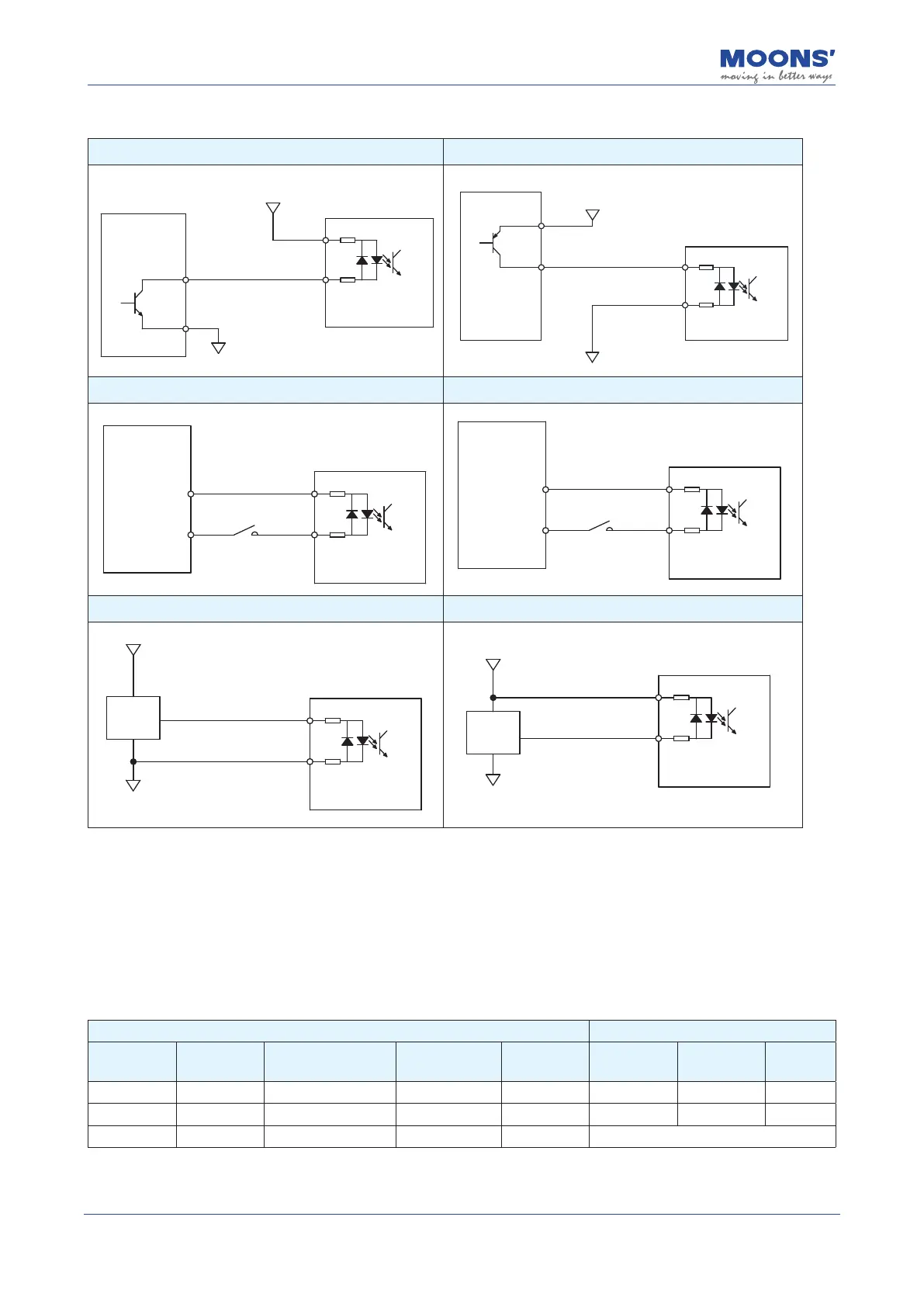
Digital input X1 ~X4 Wiring example
A. Controller---SINK mode B. Controller---Sourcing mode
XCOM
Master/Controller
5~24VDC
0VDC
2.4K
2.4K
Servo Drive
X1 ~ X4
0VDC
5~24VDC
2.4K
2.4K
XCOM
X1 ~ X4
Master/Controller
Servo Drive
C. Connect to Relay or Switch(XCOM connect to +24V) D. Connect to Relay or Switch(XCOM connect to 0V)
X1 ~ X4
Servo Drive
XCOM
24VDC
Power Supply
0V
Relay or Switch
2.4K
2.4K
X1 ~ X4
XCOM
0V
2.4K
2.4K
Servo Drive
24VDC
Power Supply
Relay or Switch
E. Connect a PNP sensor F. Connect a NPN sensor
X1 ~ X4
5~24VDC
PNP
Sensor
Signal out
0VDC
2.4K
2.4K
XCOM
Servo Drive
X1 ~ X4
5~24VDC
NPN
Sensor
0VDC
2.4K
2.4K
XCOM
Signal out
Servo Drive
4.9.3.3 Digital Outputs
The MBDV-520AC low voltage servo driver has 2 digital output signals with a common voltage
(COM) point. Each digital output signal can be congured to have a special xed function. If a xed
function is assigned to an output, you may also congure the logic of the output.
The maximum input voltage for the outputs is 30 VDC, and the maximum withstand current is 100
mA per output.
Signal Factory default
CN2-pin
number
Signal name Signal description
Corresponding
parameters
Instruction Signal name
Output logic
*1
Defaults
15 Y1 Digital output 1 P5-12 MO1 ALM Open 2
16 Y2 Digital output 2 P5-13 MO2 SON-ST Closed 7
14 YCOM Digital output COM - Y1, Y2 Output common