43
Rev. 2.0
07/27/2023
MBDV Hardware Manual
Note:
*1.
The denition of logic states for inputs and outputs is as follows:
Closed: The driver digital input circuit forms a loop, and current ows in or out of the input pins.
Open: The driver digital input circuit does not form a loop and no current ows into or out of the
input pins.
2. For details, please see: 7.1.1 Input signal setting
◆
Digital Input and Output Wiring Instructions (MBDV-520AC)
The MBDV-520AC has 4 optically isolated, single-ended inputs with a common voltage (COM)
point
These inputs require that they be powered separately. If using a PLC, you may use the 24 V
output from the PLC. If connected to a relay or mechanical switch, a 24 VDC power supply will be
required. The maximum withstand current for each input is 20 mA.What is COM?
Common (COM) represents an a common voltage level for inputs (XCOM) or outputs (YCOM). If
using sourcing signals (PNP), COM should be connected to ground (power source negative). If
using sinking signals (NPN), COM should be connected to positive voltage (positive probe from
power source).
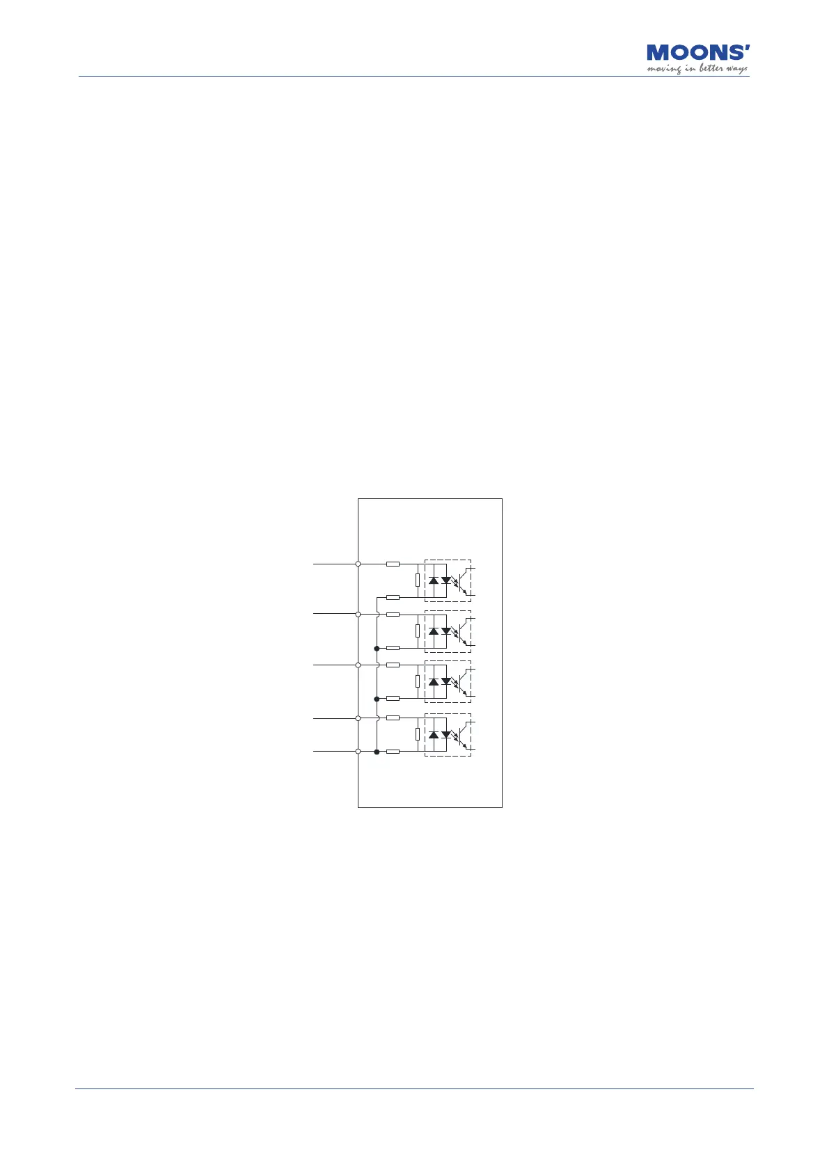
◆
The internal circuit block diagram of X1 ~ X4 is shown in the gure below.
9
X1
10
X2
11
X3
12
X4
13
XCOM
2.4KΩ
2.4KΩ
2.4KΩ
2.4KΩ
2.4KΩ
2.4KΩ
2.4KΩ
2.4KΩ