MultiSmart Installation & Operation Manual
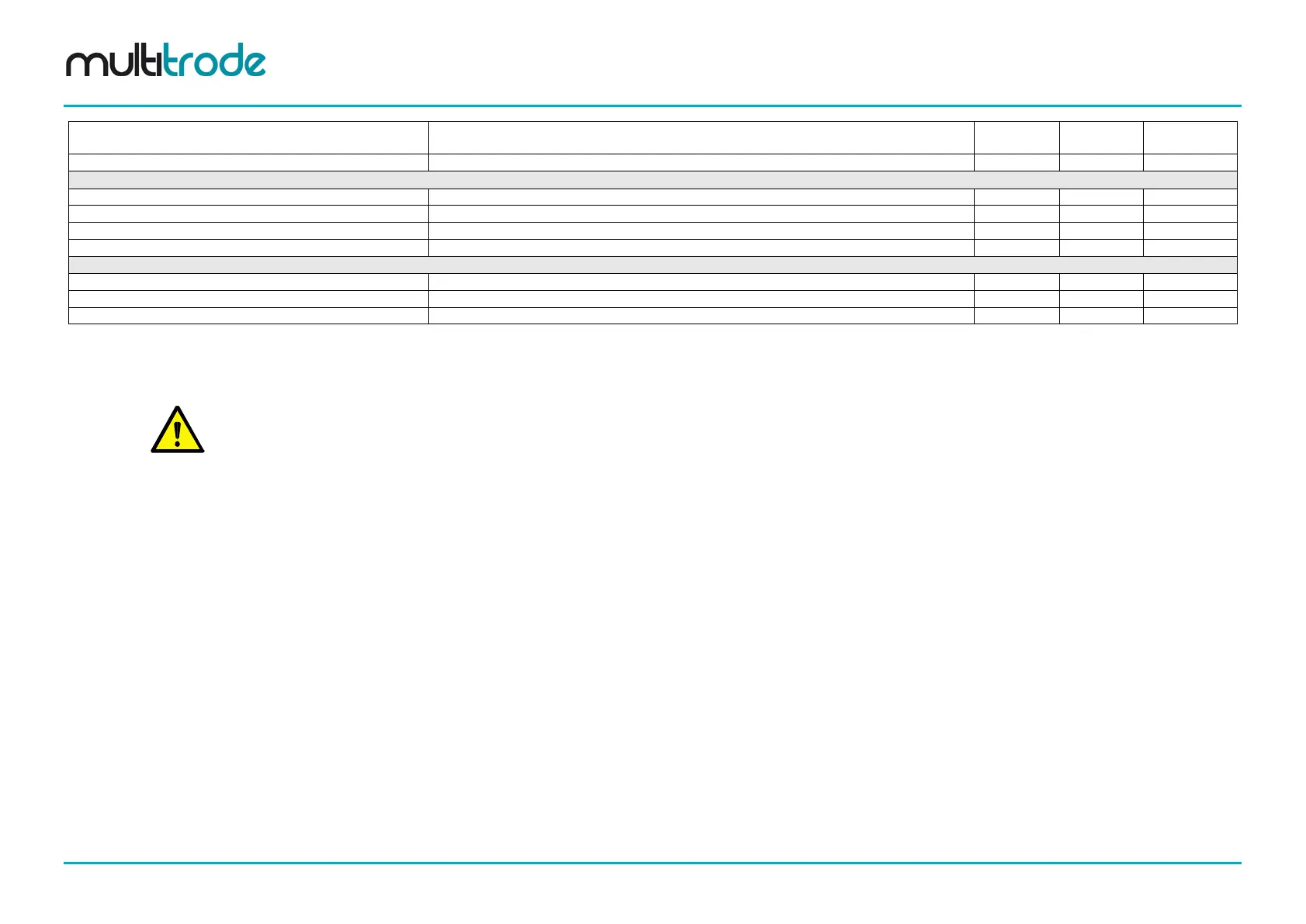
Fault Name Description
percentage of the expected flow, to give a warning to the operator
IO Unit 1 Ain 1 Over Range
Analog input current is greater than the specified maximum
IO Unit 1 Ain 1 Under Range
Analog input current is less than the specified minimum
IO Unit 1 Ain 2 Over Range
Analog input current is greater than the specified maximum
IO Unit 1 Ain 2 Under Range
Analog input current is less than the specified minimum
Generator faults
(No default Sources are linked to these faults)
Generator supply is currently being used
A predefined fault for a rain gauge
1. The Low Range Limit is found under: Advanced / IOModule / Unit / Unit 01 / Probe / Probe01 / Duo Probe / Low Range Limit.
2. These are the default inputs only when Thermal/Seal inputs are selected as part of the Setup Wizard.
3. These are the default inputs only when Flygt FLS inputs are selected as part of the Setup Wizard.
4. These faults are specific to each profile.
5. The Inhibit faults (Station & Pump) can be overridden by a digital input (if configured) (e.g. Station Inhibit Override or Pump x Inhibit))
Page 240 of 260 MultiSmart_IO_Manual_R20