Getting Started
27
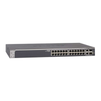
S3300 Smart Managed Pro Switch
Power/Status LED
The Power LED is a bicolor LED that serves as an indicator of power and diagnostic status.
T
he following indications are given by the following LED states:
• A solid gree
n LED indicates that the power is supplied to the switch and operating
normally.
• A solid ye
llow LED indicates that system is in the boot-up stage.
• No
lit LED indicates that power is disconnected.
FAN Status LED
FAN status is indicated as follows:
• A solid ye
llow LED indicates that the fan is faulty.
• No
lit LED indicates that the fan is operating normally.
Stack ID LED
The seven Segment LED displays the unit number in green. The dot LED on the bottom right
g
lows when either the unit is a Stack Manager or Standalone (meaning that it is not
connected in a Stack).
PoE Max LED
The PoE Max LED is for the S3300-28X-PoE+ and S3300-52X-PoE+ devices.
• Of
f indicates the system has more than 7 watts (W) of PoE power available for another
PD device.
• A stead
y yellow LED indicates that less than 7W of PoE power is available.
• A b
linking yellow LED indicates the device was active in the past two minutes.
Help Access
Every screen contains a button to launch online help , which contains information to
assist in configuring and managing the switch. The
online help screens are context-sensitive.
For example, if the IP Addressing screen is open, the help topic for that screen displays if you
click Help. Figure 7, Smart Switch Web Interface on p
age 22 shows the location of the Help
link on the web interface.
User-Defined Fields
User-defined fields can contain 1 to 159 characters, unless otherwise noted in the field label
on the configuration screen. All alphanumeric and special characters can be used except for
the following (unless specifically noted for that feature):