The Membrane Panel Operation
AFP-200 PN 15511:H2 10/14/2002 105
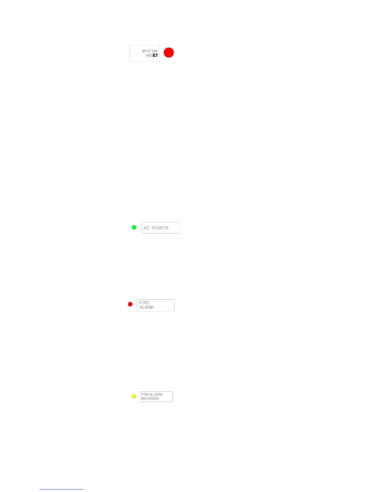
System Reset
Purpose Press the SYSTEM RESET key to reset the control panel to normal
operation (refer to “How to Operate the Panel in Normal Operation” on page 107).
Operation Pressing the SYSTEM RESET key resets the control panel by doing the
following:
• Turns off all alarm-activated control or relay modules and NAC/Panel Circuits;
• Breaks resettable power to four-wire detectors;
• Sends an “All Systems Normal” message to the LCD display, History buffer,
installed Terminal Mode LCD-80s, and installed printers; and
• Turns on all LEDs, the panel sounder, and LCD display segments for as long as the
SYSTEM RESET key is held (lamp test).
Note: Any alarm or trouble that exists after System Reset will resound the system.
4.2.5 How to Read System Status LED Indicators
The Membrane Switch Panel (see Figure 97 on page 102) contains six System Status
LED Indicators. The following provides the functions of each LED, the conditions that
cause each LED to light (steady and flashing), and how to turn off each LED.
AC Power
Function The AC POWER green LED lights steady if AC power is applied to the
control panel.
When it lights When you apply AC power to the control panel.
To turn off Disconnect AC power to the control panel.
Fire Alarm
Function The FIRE ALARM LED indicates the non-acknowledged fire alarm exists
in the system.
When it lights The FIRE ALARM LED flashes when one or more
non-acknowledged fire alarms occur. The
FIRE ALARM LED lights steady when you
press the
ACKNOWLEDGE/STEP key.
To turn off Press the SYSTEM RESET key.
Pre-Alarm Warning
Function The PRE-ALARM WARNING LED indicates that a programmed Pre-Alarm
level is reached. For details on Pre-Alarm, refer to Appendix G “Pre-Alarm
(AWACS™) Applications”.
Technical Manuals Online! - http://www.tech-man.com

 Loading...


