Main Assemblies System Overview
AFP-200 PN 15511:H2 10/14/2002 17
1.4 Main Assemblies
The AFP-200 main assemblies include the CPU board, the cabinet for enclosing the
control panel, the transformer assembly, and the batteries.
1.4.1 CPU Board
The control panel circuit board contains the system’s central processing unit (CPU),
power supply, and other primary components. The CPU is delivered pre-mounted in the
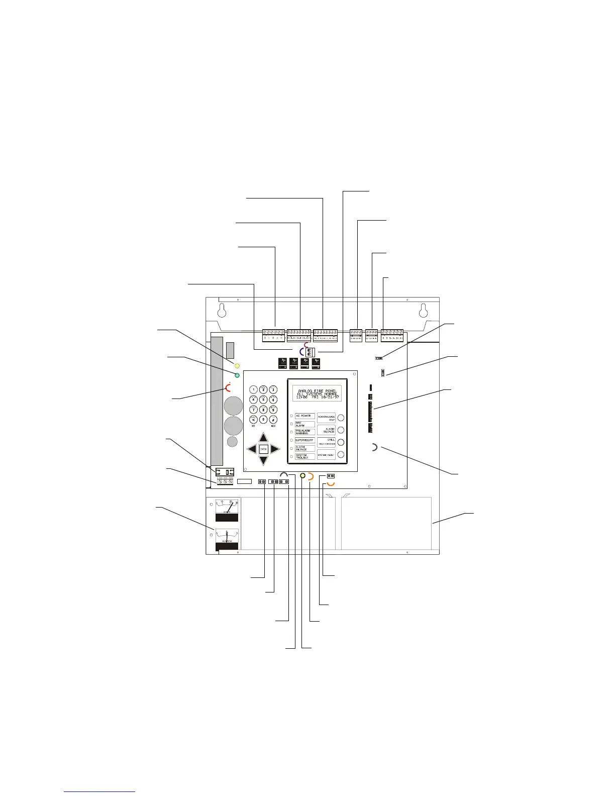
cabinet. Figure 3 shows the components of the CPU board, such as terminals, LEDs,
and connectors. For details of the membrane switch panel, see Figure 2 on page 15.
Figure 3 Connections and Controls (Shown Without Dress Panel)
Afp2incab
JP2
JP7
JP5
SW3
SW2
JP3
JP9
JP1
JP6
JP2 External charger
(cut if using CHG-120
external charger)
Battery Trouble LED
(yellow)
High Rate Charge LED
(green)
JP1 Ammeter option (cut if ammeter installed)
CB1 Circuit Breaker
J3 battery – refer to 2.4.2 “Battery
Power Connection (J3)”.
4XMM Meter
Module option
(refer to “Meter
Module” on page
20)
SW2 EIA-485 Select
switch (left =Terminal;
right =ACS)
SW3 AC Delay
Reporting
TB3 Relays – refer to “Standard Relays
(TB3)” on page 36
TB2 Notification Appliance Circuits– refer
to “Output Circuits (TB2)” on page 35
TB1 DC power – refer to “DC Output
Power Connections (TB1)” on page 35
TB7 AC Power (refer
to “AC Power
Connections (TB7)”
on page 33)
J4 Ammeter connector
J11 APS Supervisory/Tamper Switch
J2 Voltmeter connector
JP5 Option board
(cut jumper if option
board installed)
JP9 Ground fault (cut jumper to
disable ground fault detector)
Ground Fault LED (yellow)
JP3 Tamper – cut jumper to enable supervision
for expansion power supply (Appendix J
“Expansion Power Supplies”) or for tamper switch
JP6, JP7 External power –
cut jumpers if AVPS-24 or
APS-6R installed (refer to
Appendix J “Expansion
Power Supplies”)
J10 External power supply connection for
AVPS-24 or APS-6R (refer to Appendix J
“Expansion Power Supplies”)
Batteries (two
12 AH batteries
shown)
J6-J-8 Option module
slot (refer to “Option
Module: Transmitter
Module - 4XTM” on page
20
TB4 EIA-232 connections – refer to
“EIA-232 Devices – Remote Printers and
CRTs (TB4)” on page 37
TB5 EIA-485 connections – refer to
Appendix C “Annunciators” Annunciators
TB6 SLC connections – refer to “Wiring a
Signaling Line Circuit (SLC)” on page 41
Technical Manuals Online! - http://www.tech-man.com
 Loading...


