Installation Checklist Installation
AFP-200 PN 15511:H2 10/14/2002 31
2.2 Installation Checklist
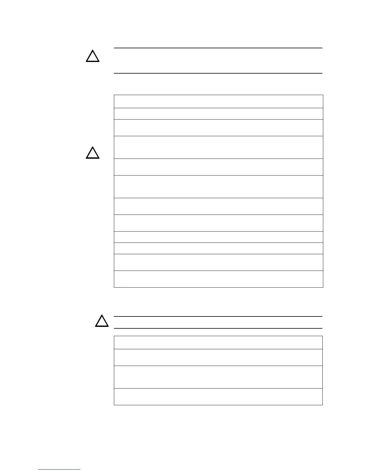
CAUTION: Make sure to install system components in the precise order in the
checklist. Failure to do so can damage the control panel and other system
components
Table 6 contains an installation checklist for installing, wiring, and testing an AFP-200
system:
Table 6 Installation Checklist
Table 7 contains a checklist for checking the system with AC power applied:
CAUTION: While checking AC power, make sure batteries are not connected.
Table 7 AC Power Checklist
Task Refer to
Mount the cabinet backbox to the wall. “Backbox Mounting” on page 32
If using expansion power supplies, mount the
expansion power supply to the backbox.
Appendix J “Expansion Power
Supplies”
CAUTION: Connect the AC power cable and DC
battery cables.
CAUTION: Do not connect power at this time!
“AC and DC Power Connections”
on page 33
Mount an optional module (RTM-8 or 4XTM). “Option Module Installation” on
page 61
Install optional peripheral devices, such as a printer,
personal computer, or CRT-2 terminal.
“EIA-232 Devices – Remote
Printers and CRTs (TB4)” on
page 37
Wire the Signaling Line Circuits. “Wiring a Signaling Line Circuit
(SLC)” on page 41
Connect AC power to control panel — but do not
connect batteries.
“AC Power Connections (TB7)”
on page 33
Check AC power—but do not connect batteries. Table 7
Program the control panel. Section 3 “Programming”
Connect the batteries. “Battery Power Connection (J3)”
on page 34
Walk test the system. “How to do a Walk Test (6=walk
test)” on page 99
Component Status
The CPU The green AC Power indicator on; the system Trouble indicator
on because of no battery power.
option module The yellow Trouble indicator may come on for approximately 10
seconds after applying AC power. (This only applies to an
unconfigured system.)
AVPS-24/AVPS-24E
or APS-6R
The yellow Trouble indicator comes on because batteries are
not connected.
!
!
!
Technical Manuals Online! - http://www.tech-man.com
 Loading...


