The Main Power Supply Power Supply Calculations
AFP-200 PN 15511:H2 10/14/2002 127
A.3 The Main Power Supply
The control panel's main power supply can supply a total of 5.0 A in alarm and 1.0 A in
standby (Non-Alarm condition). The current available for powering external devices,
however, is subject to lower limits as shown in Figure 126 and Figure 127.
A.3.1 Current Limitations in Standby
Current for operating an external device in standby (Non-Alarm) is subject to the
following limitations:
1. Non-resettable power (TB1, terminals 3 and 4) and resettable power (TB1,
terminals 5 and 6) are limited to a combined total of 0.5 A. Using Table 47,
Calculation Column 1, verify that the combined subtotal of rows 4 and 5 is less
than 0.5 A.
2. The total power supply load is limited to 1.0 A. Using Table 47, verify that the
total of Calculation Column 1 is less than 1.0 A.
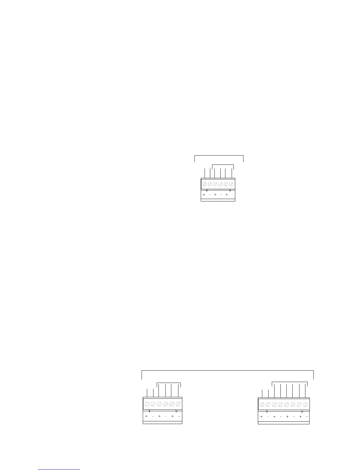
Figure 126 TB1 Standby Current Limitations
A.3.2 Current Limitations in Alarm – System Operation on
Primary Power
Current for operating external devices in alarm is subject to the following limitations:
1. High ripple power (TB1, terminals 1 and 2) is limited to 1.5 A. Using Table 47
Calculation Column 2, verify that the subtotal of row 4 is less than 1.5 A.
2. Non-resettable power (TB1, terminals 3 and 4) and resettable power (TB1,
terminals 5 and 6) are limited to a combined total of 0.5 A. Using Table 47
Calculation Column 2, verify that the subtotal of rows 5 and 6 combined is less
than 0.5 A.
3. The maximum load on NAC 1 (TB1, terminals 1 and 2) cannot exceed 2.5 A.
Using Table 47 Calculation Column 2, verify that the subtotal of row 7 is less than
2.5 A.
4. The maximum combined load on NAC 2, NAC 3, and NAC 4 (TB2,
terminals 3-8) cannot exceed 2.5 A. Using Table 47 Calculation Column 2, verify
that the subtotal of row 8, 9, and 10 is less than 2.5 A.
5. The total power supply load is limited to 5.0 A. Using Table 47, verify that the
subtotal for Calculation Column 2 is less than 5.0 A.
Figure 127 TB1 and TB2 Alarm Current Limitations
1
23456
0.5 A combined
TB1
1.0 A Total System
1
2345678
1
23456
0.5 A combined
2.5 A
5.0 A Total System
TB2
2.5 A combined
TB1
1.5 A
Technical Manuals Online! - http://www.tech-man.com

 Loading...


