System Overview Main Assemblies
18 AFP-200 PN 15511:H2 10/14/2002
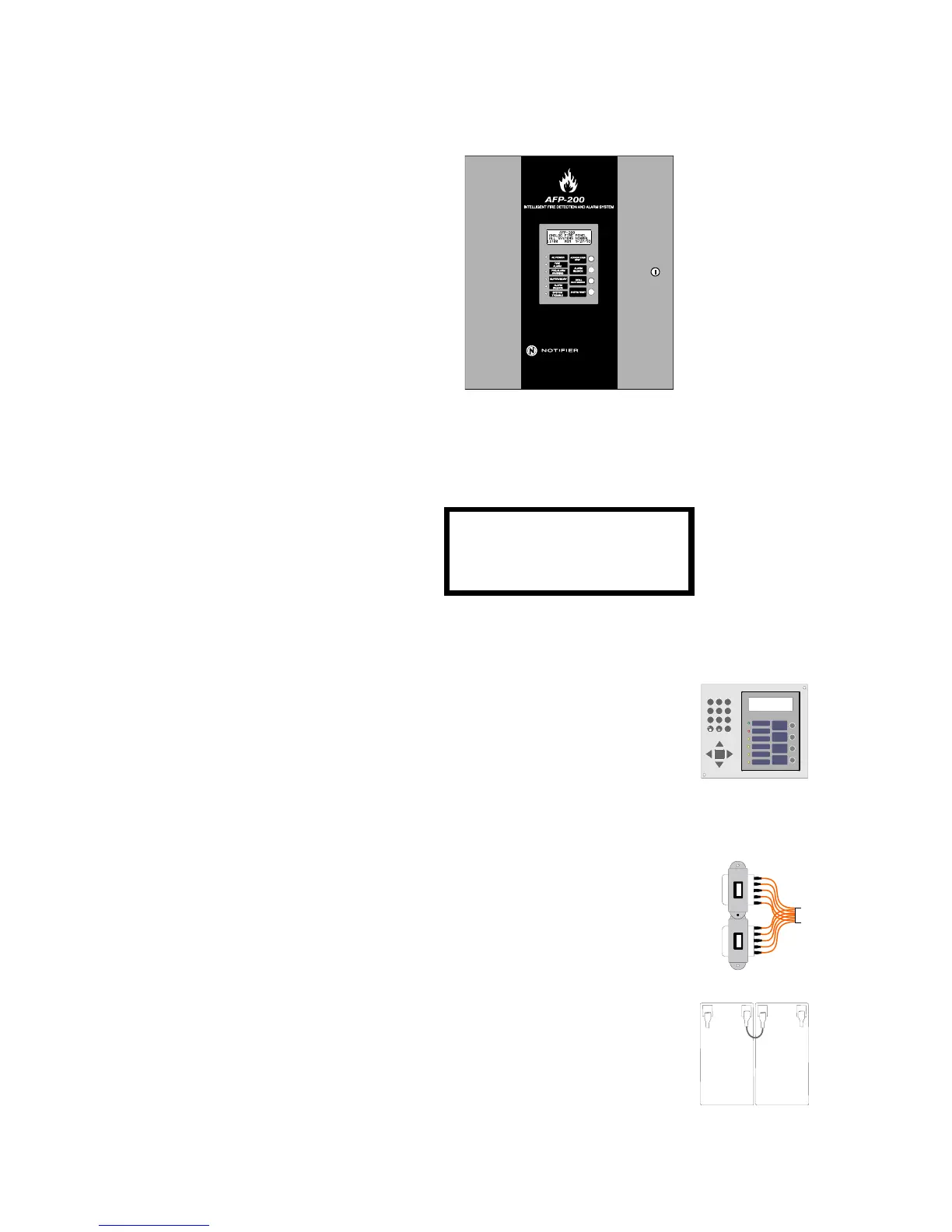
1.4.2 Cabinet
The CPU board mounts in a compact (16.125" x 14.5" x 5.5") cabinet with a front dress
plate. The cabinet provides space for two batteries (up to 12 AH).
1.4.3 LCD Display
The control panel uses an 80-character LCD display (4 rows of 20 characters each). The
display includes a long-life LED backlight that remains on unless AC power is lost
while the system is not in alarm:
Figure 4 LCD Display
1.4.4 Membrane Switch Panel
The membrane switch panel provides LED Status
Indicators, operator keys, and programming keys. The
operator keys and LEDs are visible with the cabinet door
closed. The programming keys are visible only with the
door open. Slide-in labels are provided for switch and
LED descriptions. Refer to “Membrane Switch Panel” on
page 15.
1.4.5 Transformer Assembly
The transformer assembly includes two 100 VA
transformers and a connector.
1.4.6 Batteries
The cabinet provides space for 7 AH or 12 AH batteries
(for 18 AH batteries use the BB-17 battery box). Batteries
must be ordered separately.
AFP-200
ANALOG@FIRE@PANEL
ALL@SYSTEMS@NORMAL
11:00@MON@5/19/98
ENTER
ACKNOWLEDGE
STEP
ALARM
SILENCE
DRILL
HOLD 2 SECO NDS
SYSTEM
RESET
AC POWER
FIRE
ALARM
PRE-ALAR M
WARNING
SUPERVISO RY
ALARM
SILENCE
SYSTEM
TROUBLE
DET MOD
12
3
4
5
6
789
#
A
B
C
D
E
F
G
H
I
J
K
L
M
N
O
P
R
S
T
U
V
W
X
Y
Q
Z
-
/
.
ALL SYSTEMS NORMAL
09:45A THU 06/18/97
M
 Loading...


