Installation Option Module Installation
62 AFP-200 PN 15511:H2 10/14/2002
2.10.2 Installing a 4XTM Module
Install the 4XTM module onto the CPU board as follows:
1. Insert the two nylon standoffs (provided) into the holes located on the right-side
edge of the main circuit board.
2. Carefully align the pins on the circuit board with the connector on the option
board; then, press firmly on the option board until it locks in place on the standoffs.
3. Stick the provided labels on the 4XTM module.
4. Push the disconnect switch (Figure 45) down to prevent unwanted activation of the
municipal box during testing of the control panel.
The Disconnect LED remains lighted while the municipal box is disconnected. The
System Trouble LED will indicate disconnected and/or open circuit conditions on
the municipal box. During trouble conditions, it is possible to obtain the circuit
condition on the alarm reverse-polarity output. If this operation is desired, cut the
TBL jumper (shown in Figure 45)
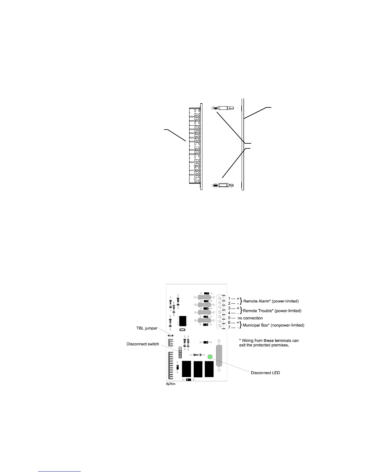
Figure 45 shows 4XTM module components with polarities shown in activated
positions.
Figure 45 4XTM Module Connections and Components
Standoffs
4XTM Option Board
CPU Board
Polarities are shown in
activated positions.
Technical Manuals Online! - http://www.tech-man.com

 Loading...


