System Overview End-of-Line Devices
24 AFP-200 PN 15511:H2 10/14/2002
1.8 End-of-Line Devices
1.8.1 Overview
Table 4 contains a list of the end-of-line devices that you can install in an AFP-200
system:
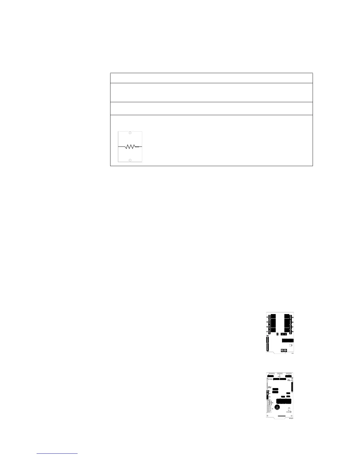
Table 4 End-of-Line Devices
1.9 Annunciation Modules
1.9.1 Overview
For instructions on installing
annunciation modules, refer to
Appendix C “Annunciators” on
page 140.
This section contains brief descriptions and the model numbers of annunciator modules
that can be connected to the control panel. Communication between the control panel
and annunciators takes place over a two-wire serial interface connected to an EIA-485
connector (TB5) on the CPU. For detailed wiring requirements, refer to the appropriate
annunciator manuals.
Canadian Requirement: The ACM Series annunciator modules must be used to
annunciate the fire alarm input points/zones only. For Canadian applications, the
following LED colors must be employed:
• Red must be used to indicate active alarm inputs
• Yellow must be used to indicate supervisory, burglary or trouble signals
• Green must be used to indicate the presence of power or an activated output
1.9.2 Annunciator Control Module-8R (ACM-8R)
The ACM-8R provides the AFP-200 with a mappable
relay control module. ACM-8R relays can be selected for
mapping anywhere in the system memory map (in groups
of eight). Features of the ACM-8R include the following:
• Provides eight Form-C relays with 5 A contacts.
• Tracks any group of eight zones within the system.
1.9.3 LDM Series Lamp Driver Modules
The LDM-32 Lamp Driver Annunciator Module provides
32 alarm lamp driver outputs for connection to a custom
graphic annunciator. You can also set the LDM-32 with a
DIP switch for 16 alarm, 16 trouble and 16 switch inputs
for control of such system functions as Signal Silence and
System Reset.
• Lamp Driver Annunciator Expander Module
Option Description Notes
A2143-00
(System Sensor)
A 47K End-Of-Line Resistor (ELR) Assembly
ELR used in the supervision of monitor,
control and relay module circuits.
Supplied with monitor, control
and relay modules.
A2143-10
(System Sensor)
The 3.9K End-Of-Line Resistor (ELR) Assembly
used with two-wire detector modules.
Supplied with two-wire detector
modules.
N-ELR Resistor
plate (Notifier)
An N-ELR, required for Canadian
installations, provides connection for a
resistor to mount to an ELR plate.
• Use 4.7K for the NAC
circuits.
• Use 47K for monitor, control
and relay modules.
Technical Manuals Online! - http://www.tech-man.com

 Loading...


