Installation Backbox Mounting
32 AFP-200 PN 15511:H2 10/14/2002
2.3 Backbox Mounting
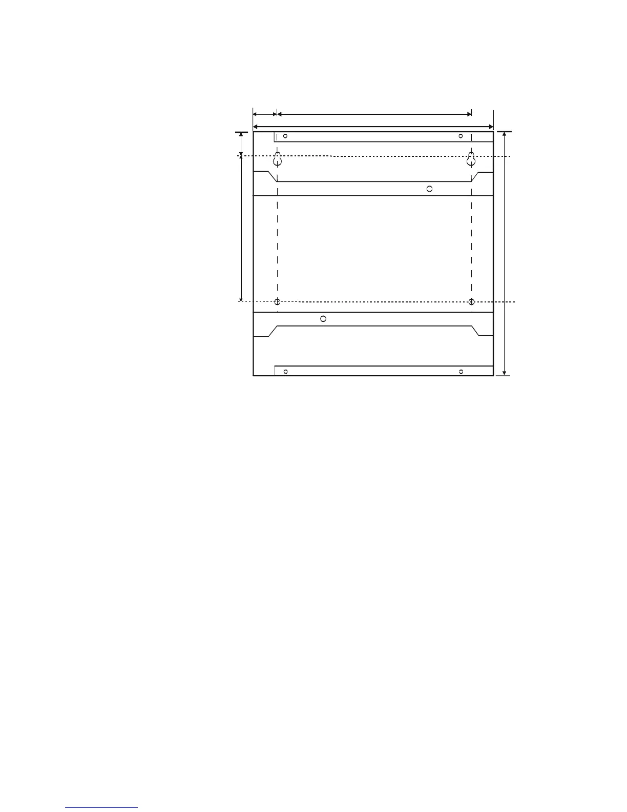
Figure 8 shows the dimensions of the cabinet backbox:
Figure 8 Backbox Dimensions
1. Remove the CPU board assembly by unscrewing the four screws in the corners of
the board. Set the CPU board aside in a safe, clean place. Avoid static discharge
which may damage the board.
2. Mark and predrill the four mounting bolts using dimensions shown in Figure 8.
3. Install two upper fasteners in wall with screw heads protruding.
4. Using upper keyholes, mount the backbox over the two screws. Tighten the screws.
5. Install and tighten the lower two screws.
6. When location is dry and free of construction dust, reinstall the CPU board.
afpcabdim.cdr
16.0"
(40.64 cm)
9.5"
(23.495 cm)
0.5"
(1.27 cm)
12.5" (31.75 cm)
14.5" (36.83 cm)
1.0"
(2.54 cm)
Technical Manuals Online! - http://www.tech-man.com
 Loading...


