Option Module Installation Installation
AFP-200 PN 15511:H2 10/14/2002 61
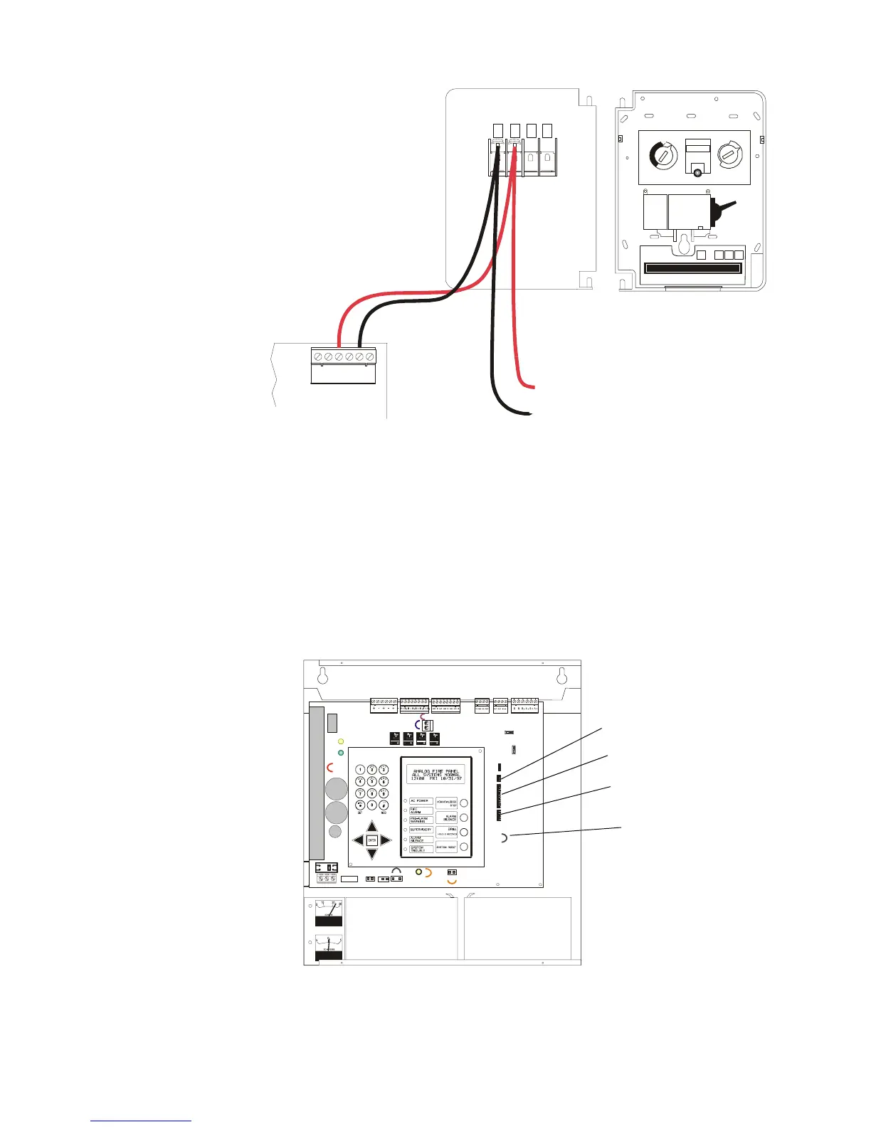
Figure 43 Typical SLC Wiring of an NBG-12LX Pull Station
2.10 Option Module Installation
2.10.1 Overview
The control panel has an option module slot, using connectors J6, J7, and J8 on the
CPU board. Two optional modules are available for the control panel: the 4XTM
Transmitter Module and the RTM-8 Relay Module. To enable module supervision, you
must cut jumper JP5 before installing an option module. Figure 44 shows the location
of the connectors and jumper J5.
Figure 44 Optional Module Location
1 2 3 4
TB6
1
23456
+
-
CPU of Control Panel
SLC (+) TB 6-3
SLC (–) TB 6-5
NBG-12LX
(rear view)
(+)
(-)
To next device on
SLC loop
N
O
R
M
A
L
A
C
T
I
V
A
T
E
D
4 3 2 1
0
0
10
11
12
13
14
15
1
1
2
2
3
3
4
4
TENS
ONES
6
6
7
7
8
8
9
9
5
5
LOOP
M
 Loading...


