Wiring a Signaling Line Circuit (SLC) Installation
AFP-200 PN 15511:H2 10/14/2002 49
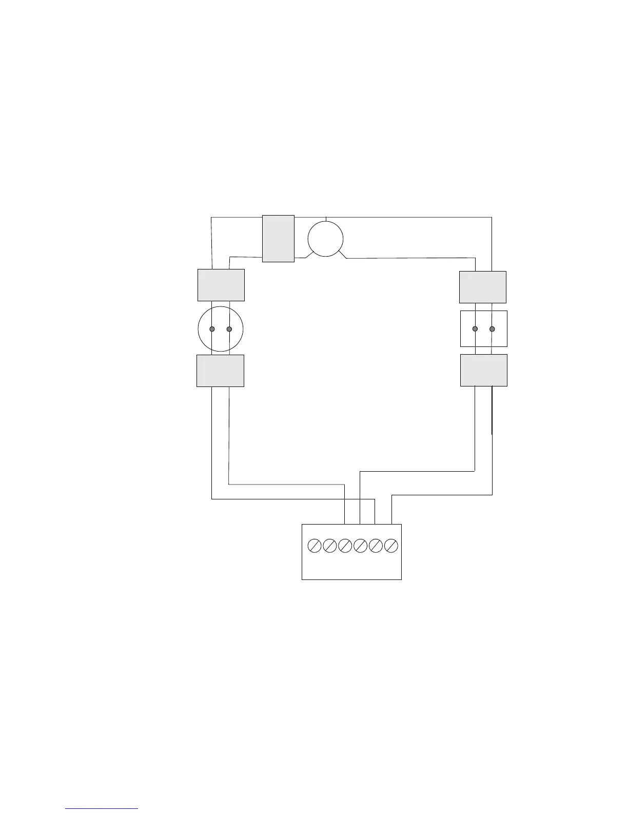
Style 7 Wiring Overview
Figure 29 shows typical wiring of a four-wire SLC that meet NFPA Style 7
requirements. As shown in Figure 29, flanking each SLC device with a pair of ISO-X
isolator modules protects each device from short circuit faults that may occur on other
SLC devices. For example, a fault on zone 2 will not affect zones 1 and 3. ISO-X
modules on either side of zone 2 will open the SLC. Zone 1 will still operate from
power on loop out and zone 3 will operate from SLC return. Because the control panel
cannot communicate with zone 2, a trouble signal(s) will be generated for that device.
Note: Do not T-Tap or branch a Style 7 four-wire SLC. Ratings and characteristics are
identical to a NFPA Style 6 four-wire SLC.
Figure 29 Four-wire SLC (Style 7)
2.9.9 Wiring an Isolator Module (ISO-X)
ISO-X Module Overview
You can connect a maximum of 25 devices between isolator modules. During a fault
condition, the control panel registers a trouble condition for each addressable device
which is isolated on the SLC segment or branch.
Refer to 2.9.6 “Setting an SLC Address for a Module” for instructions on addressing
the modules.
Addressable Manual
Pull Station (flanked by
ISO-X modules)
Note: All wiring between
a manual pull station
and ISO-X modules
should be enclosed in
conduit.
Note: If a non ISO base
is used, install ISO-X
modules on both sides
of devices within 20 feet
(6.096 m) in rigid
conduit.
Note: Locate ISO-X
module near detector.
Enclose wiring between
detector and ISO-X in
conduit.
CPU
Connect SLC Out to
TB 6-3 (+) and TB 6-5 (–).
Connect SLC Return to
TB 6-4 (+) and TB 6-6 (–).
SLC Out
SLC Return
Addressable
Detector
(Zone 1)
Two-wire Isolator
Detector Base
(Zone 2)
Addressable
Pull Station
(Zone 3)
Control Panel
ISO-X
ISO-X
ISO-X
ISO-X
ISO-X
_
+
_
+
1
2
3
4
5
6
A+BB+ B-A-A
1
2
34
1
2
34
1
2
3
4
1
2
3
4
1
2
3
1
2
3
4
Technical Manuals Online! - http://www.tech-man.com

 Loading...


