NFPA Applications Central Station Fire Alarm Systems (Protected Premises)
134 AFP-200 PN 15511:H2 10/14/2002
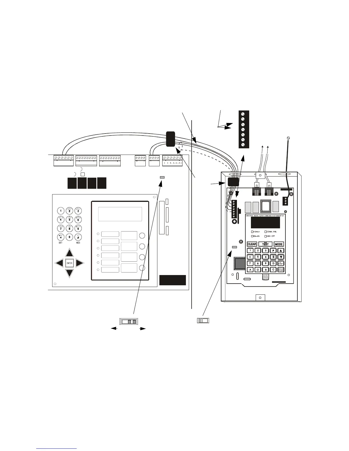
B.2.2 Installing a UDACT
Figure 130 shows typical connections for wiring a UDACT to the control panel. For
detailed wiring, configuration, and programming instructions for the UDACT, refer to
the UDACT manual. When finished installation, review the checklist below.
Note: This application requires compatible system software—the UDACT must have
software PN 73624 or higher and the control panel must have software PN 73609 or
higher. Also, add the UDACT current into the control panel power supply calculations
(refer to Appendix A “Power Supply Calculations”).
Figure 130 NFPA 72 Central Station Fire Alarm System – UDACT
(Protected Premises Unit)
To install a UDACT to the control panel, follow these steps. Check that all items are
answered before powering the UDACT or control panel:
1. Is the UDACT connected to non-resettable 24 VDC power on the control panel
[TB1, terminal 3 (+) and terminal 4 (–)] with correct polarity (Figure 130)?
2. Is the UDACT connected to the EIA-485 port on the control panel, [TB5, terminal
1 (+) and terminal 2 (–)] with correct polarity (Figure 130)?
3. Is the UDACT ACS/TERM switch set to the ACS (left) position (Figure 130)?
4. Is the UDACT Start Monitor Address set to 1 and is the Stop Monitor Address set
TEST
CONNECTOR
J5
J8
PH1
PH2
J9
SECONDARY
ACTI VE
+24V
+24V
1
2
3
4
5
6
7
+24V
COMM
FAI L
EARTH
GND
GND
GND
TB1
TB1
TB3
RS+
RS+
RS+
RS+
RS-
RS-
RS-
RS-
SHIELD
SHIELD
PRIMARY ACTIVE
T
B
3
T
B
2
T
B
1
T
B
6
TX REF RX RE F
OUT OUT IN IN
T
B
5
T
B
4
JP8
JP8
1
11
1
1
1
2
2
2
2
2
2
3
33
3
3
3
4
4
4
4
4
4
5
5
5
5
6
6
6
6
7
7
8
8
AC POWER
FIRE
ALARM
PRE-ALARM
WARNING
SUPERVISORY
SECURITY
ALARM
SILENCED
SYSTEM
TROUBLE
ACKNOWLEDGE
STEP
ALARM
SILENCE
EVACUATE
HOLD 2 SECONDS
SYSTEM RESET
AFP-200
ANALOG FIRE PANEL
ALL SYSTEMS NORMAL
12:00 FRI 8/14/92
+ - + - + -
B+ B- B+ B- B+ B- B+ B-
NO C N0 NC C N0 NC C
+
+
+
-
-
-
Afp200ab
Note: If this is the last or only device on the line,
install a 120 ohm end-of-line resistor (PN 71244)
on TB1 terminals 3 and 4 as shown.
solid earth
ground
connection
to phone
lines
(supervised)
Ferrite
Cores
PN 29090
supervised and power-limited
EIA-485 and power wiring
AFP-200
AFP-200
Cabinet
UDACT in ABS-8R
(shown with cover removed)
ACS/TERM switch
ACS TERM
ACS
TERM
SW2
Technical Manuals Online! - http://www.tech-man.com
 Loading...


