Option Module Installation Installation
AFP-200 PN 15511:H2 10/14/2002 63
2.10.3 Installing an RTM-8 Module
Install the RTM-8 module onto the CPU board according to the following directions. If
the FACP is in a high vibration area where additional support is desired, install the
RTM-8 with a DP-AFP200 Dress Panel, using every step in Figure 46 below. Steps 4
and 8 are not necessary if a dress panel is not installed.
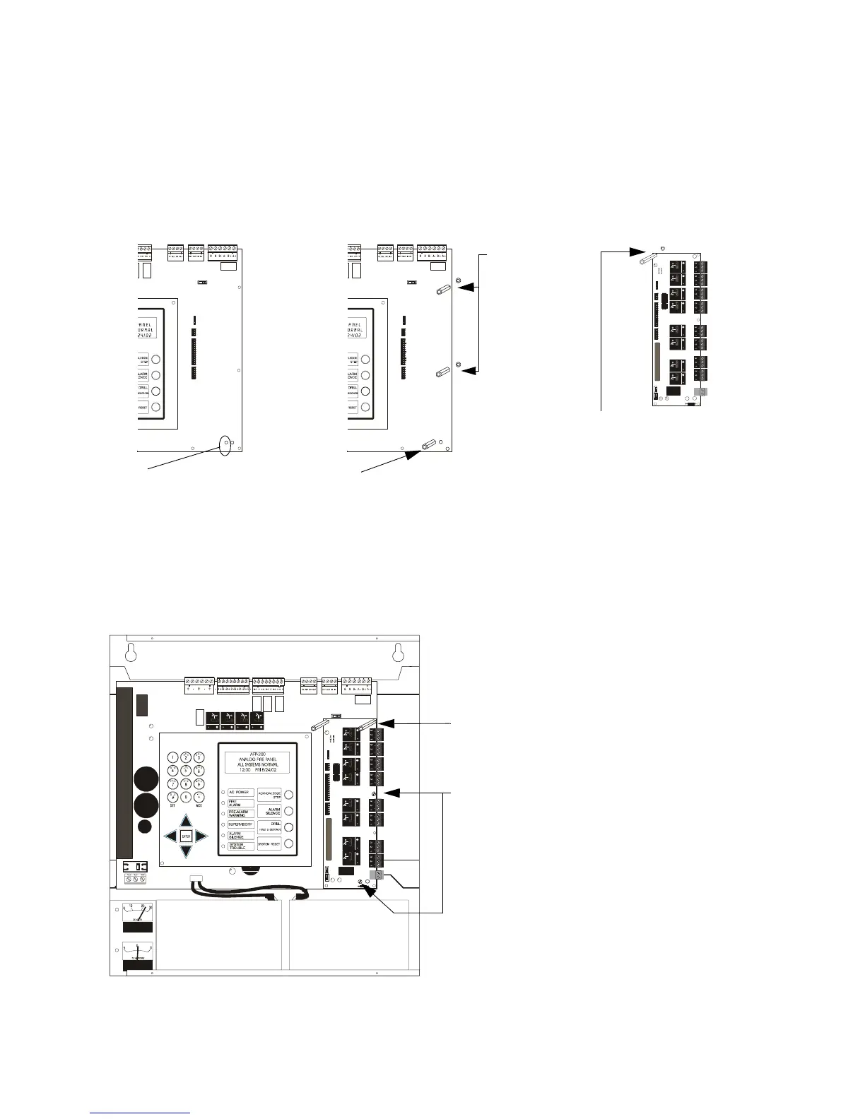
Figure 46 RTM-8 Relay Module Installation
AFP-200 CPU
1. Remove screw from lower
right corner of the AFP-200
CPU board. Reserve the
screw for later use.
Note: Remember that jumper
JP5 must be cut to enable
module supervision (See
Figure 44 on page 61. )
2. Replace the screw with one
of the three short (1/2 in, 12.7
mm) metal standoffs supplied
with the RTM-8 module.
AFP-200 CPU
3. Place the
other two short
metal standoffs
into the AFP-200
CPU holes as
indicated.
Fasten them
with two of the
nuts supplied
with the RTM-8
module.
4. Note: Use this step only
when using a DP-AFP200
dress panel.
Attach one of the two long
(15/16 in, 23.8 mm) metal
standoffs to the upper left
corner of the RTM-8 as
indicated. Fasten with the
third nut supplied.
5. Carefully align the pins on the circuit board with the
connector on the RTM-8 module; then press firmly on the
module until it locks in place and rests on the standoffs
installed in steps 2 and 3 above.
6. Secure the upper right corner of the RTM-8 with the
(remaining) long metal standoff.
7. Using the screw removed from the AFP-200 CPU and the
screw supplied with the RTM-8, secure the module to the
CPU at the points indicated.
8. Note: Use this step only when using a DP-AFP200 dress
panel.
Install the DP-AFP200 Dress Panel per instruction document
supplied with the dress panel. This installation provides extra
mounting support for the module in areas of high vibration.
AFP2ptla.cdr
AFP2ptlb.cdr
AFP2RTM8lngstdoff.cdr

 Loading...


