Wiring a Signaling Line Circuit (SLC) Installation
AFP-200 PN 15511:H2 10/14/2002 43
2.9.4 SLC Performance
SLC performance depends on the type of circuit: Style 4, Style 6, or Style 7. Table 11
lists the trouble conditions that result when a fault exists on an SLC.
Table 11 SLC Performance
2.9.5 SLC Shield Termination
Overview
All wiring leaving the control panel must be shielded. Figure 19, Figure 20, and Figure
21 show three methods of wiring termination, depending on the type of conduit used: a)
no-conduit, b) full-conduit, and c) partial-conduit.
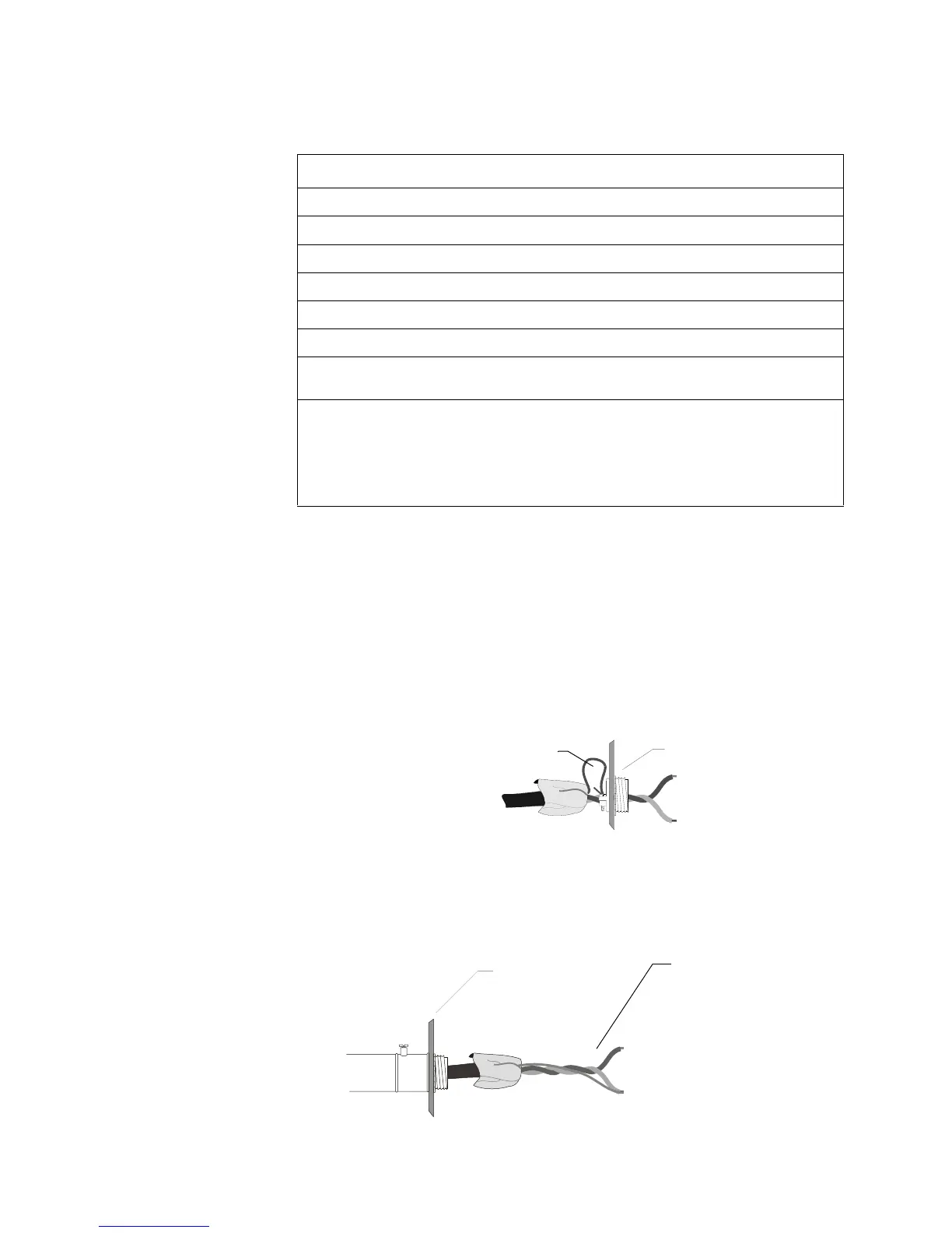
No-Conduit Shield Termination
Do not allow the shield drain wire to enter the system cabinet. Connect the drain wire to
the outside of the cabinet using a cable connector as shown in Figure 19:
Figure 19 Shield Termination – No Conduit
Full-Conduit Shield Termination
For Style 6 or Style 7 field-wiring of the SLC, connect each end of the shield to the
negative side of the respective channel as shown in Figure 20:
Figure 20 Shield Termination – Full Conduit
Fault in SLC Style 4 Style 6 Style 7
Open Trouble Alarm/Trouble Alarm/Trouble
Ground Alarm/Trouble Alarm /Trouble Alarm/Trouble
Short Trouble Trouble Alarm/Trouble
Short and open Trouble Trouble Trouble
Short and ground Trouble Trouble Alarm/Trouble
Open and ground Trouble Alarm /Trouble Alarm/Trouble
Communications
loss
Trouble Trouble Trouble
• Trouble indicates a trouble signal will be generated at the control panel during the abnormal
condition.
• Alarm/Trouble indicates an alarm signal can be transmitted to the control panel during the
abnormal condition.
• SLC operation meeting Style 7 requirements isolates entire physical zones on the SLC from
faults that occur within other areas of the SLC.
Shield Drain Wire
Scrape paint away from the
cabinet to make good
electrical connections.
shield1.wmf
SLC +
SLC -
Cabinet
Shield Drain Wire: The
shield must not be
connected to earth
ground at any point.
The shield drain wire must be
connected to the negative (–)
side of the loop. Do not let the
shield drain wire or the shield
foil touch the system cabinet.
Cabinet
shield2.wmf
SLC +
SLC -
Technical Manuals Online! - http://www.tech-man.com
 Loading...


