System Overview Optional Devices & Option Modules
20 AFP-200 PN 15511:H2 10/14/2002
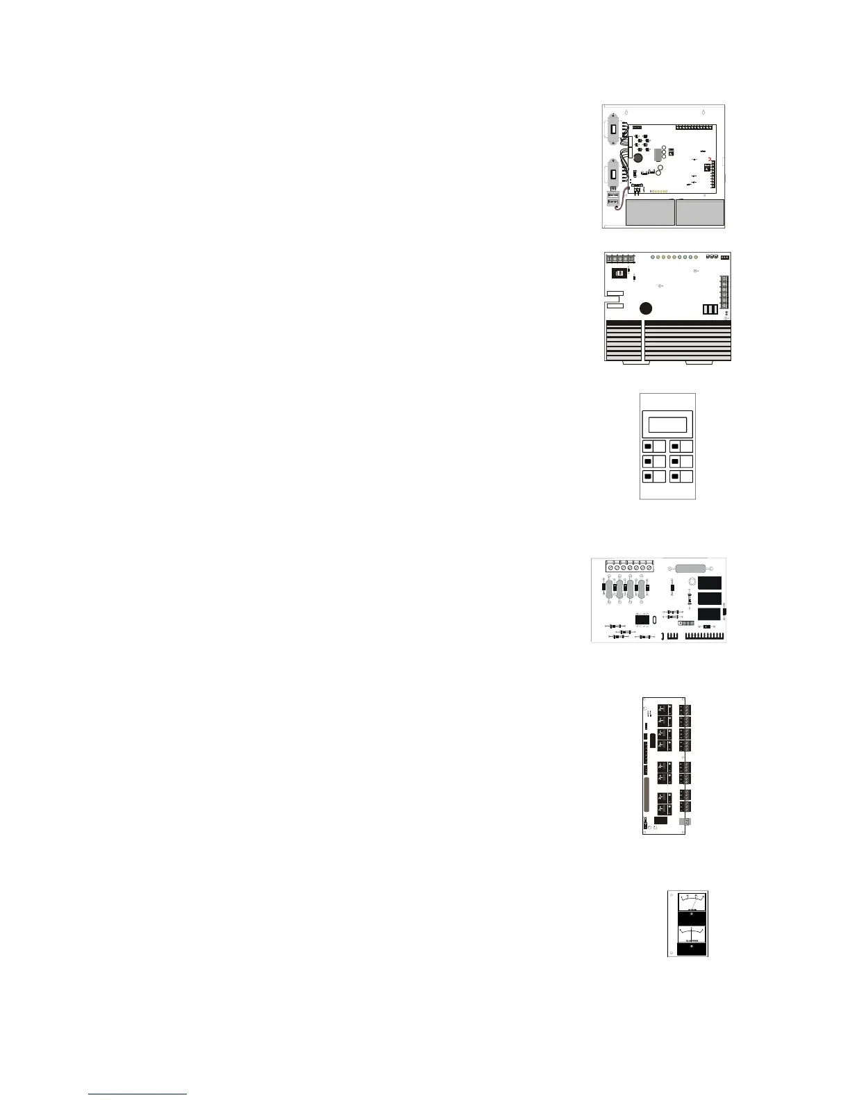
1.5.4 Field Charger/Power Supply - FCPS-24
A compact, cost-effective remote power supply and
battery charger. It consists of a filtered, 24 VDC output
that can drive up to four Notification Appliance Circuits
(NACs). Refer to the FCPS-24 Field Charger/Power
Supply manual for further information and installation
instructions.
1.5.5 Battery Charger - CHG-120
Designed to charge lead-acid batteries that provide
emergency standby power for a Fire Alarm Control Panel.
Provides two (2) output circuits for connection to multiple
loads. Can be mounted into a CAB-3 Series cabinet or a
BB-55 or NFS-LBB Battery Box. For details, refer to the
CHG-120 Battery Charger manual.
1.5.6 Liquid Crystal Display - LCD-80
An alphanumeric display module that is an ancillary
device which has two basic modes of operation. In
Terminal Mode it acts as a display interface and in ACS
Mode as an alphanumeric annunciator. The LCD-80TM is
also available and provides Term inal Mode only. Refer to
the LCD-80 manual or LCD-80TM Liquid Crystal Display
manual.
1.5.7 Option Module: Transmitter Module - 4XTM
The 4XTM provides connections to municipal box and
remote station transmitters meeting NFPA 72 Auxiliary
and Remote Station requirements. The 4XTM is
mounted on the control panel’s CPU and includes a
Disable switch and an LED indicator. Refer to 2.10.2
“Installing a 4XTM Module”.
1.5.8 Option Module: Relay/Transmitter Module - RTM-8
The Relay/Transmitter Module (RTM-8) provides eight
Form-C relays (5A contacts) that track software zones 1
through 8. The RTM-8 also provides Municipal Box and
Remote Station transmitters NFPA 72 Auxiliary and
Remote Station requirements. In remote station
applications, the RTM-8 transmits alarm only and does
not transmit trouble or supervisory status. Disable
switches and indicators are included. Refer to 2.10.3
“Installing an RTM-8 Module”.
1.5.9 Meter Module
The 4XMM Meter Module provides a voltmeter to measure
voltage across the batteries and an ammeter to measure charging
current to the batteries. A single assembly containing both meters
mounts in the lower-left corner of the AFP-200 cabinet as shown
in Figure 3 on page 17.
++ + +
+ + + + +
++ ++
++
+
+ +
+
+
+
+ +
TB2
P3
TB1
TB3
TB4
1
2
3
4
5
6
7
8
9
30
1.0
2520
.8
15
.6
10
.4
5
.2
0
0
D.C. VOLTS
D.C. AMPERES
FCPS-24assy.cdr
TB2
JP4 JP5 JP6
F3 F2 F1
SW1
R100
R104
JP8
JP9
JP3
JP7
TB3
TB1
CHG120pc.cdr
LCD80-outline.tif
4XTMassy.cdr
rtm-8.cdr
Technical Manuals Online! - http://www.tech-man.com

 Loading...


