Expansion Power Supplies Installation
180 AFP-200 PN 15511:H2 10/14/2002
J.3.2 APS-6R Calculations
Supply calculations for systems with an APS-6R follow:
• Add 2.5 A for the APS-6R and 1.2 A for the APS-6R to the AC branch circuit
current in Table 44 and Table 45.
• Do not include the load current on NAC 3 and 4 in the 5.0 A limitation in Table 47
and notes.
System alarm current limitations with an APS-6R installed follow:
• TB2, terminal 1 and 2 or J1 = 3.0 A
• TB2, terminal 3 and 4 or J2 = 3.0 A
• TB2, terminals 1, 2, 3 and 4 combined = 6.0 A
J.4 Installation
This section contains instructions for installing an AVPS-24/AVPS-24E and an
APS-6R.
J.4.1 Installing the AVPS-24/AVPS-24E
Mounting the AVPS-24/AVPS-24E
To mount the AVPS-24/AVPS-24E, follow these steps:
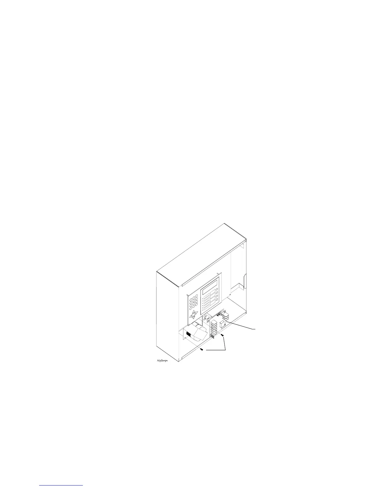
1. Place the AVPS-24/AVPS-24E into the cabinet as shown in Figure 161.
2. Insert mounting screws into cabinet; then tighten the screws until the
AVPS-24/AVPS-24E is securely fastened to the cabinet.
Figure 161 Mounting the AVPS-24/AVPS-24E
Wiring the AVPS-24/AVPS-24E
Wire the AVPS-24/AVPS-24E to the control panel according to the steps in Table 68
and the drawing in Figure 162.
Mounting screws
AVPS-24/AVPS-24E
Technical Manuals Online! - http://www.tech-man.com

 Loading...


