Optional Devices & Option Modules System Overview
AFP-200 PN 15511:H2 10/14/2002 19
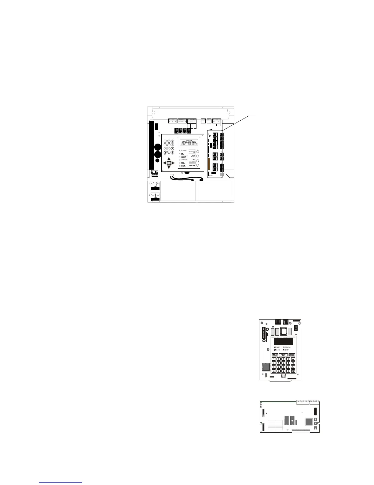
1.5 Optional Devices & Option Modules
Several optional components can be installed within this fire alarm control system,
including external devices and “option modules” that plug directly into the CPU. The
CPU board includes an option module slot located on the right side of the board. When
an option module is installed, jumper JP5 (Figure 3 on page 17) must be cut. The option
slot supports a 4XTM or RTM-8 module.
For instructions on installing an option module, refer to 2.10 “Option Module
Installation”.
Figure 5 Option Module Slot (Shown with RTM-8 Module)
Further information and installation instructions for specific devices are provided in
those product manuals; for part numbers of manuals refer to Table 3, “Supplemental
Documentation,” on page 12.
1.5.1 Digital Communicator
The 911AC Digital Alarm Communicator/Transmitter transmits three zones of
information (System Alarm, System Trouble, Supervisory) to the central station or
remote station receiver. Fully UL-listed for fire operation (NFPA 72), the 911AC
requires two standard dial-up telephone lines to operate. For details, refer to the 911AC
Manual.
1.5.2 UDACT
The UDACT transmits system status for up to 99 zones
to UL-listed Central Station Receivers over a public
switched telephone network. It mounts remotely in the
ABS-8R enclosure. The unit connects to the EIA-485
annunciator port and 24 VDC (nominal) power;
software PN 73609 or higher must be installed. Some
NFPA applications are provided in Appendix B. For
further details, refer to the UDACT manual.
1.5.3 Network Interface Board - NIB-96
A microprocessor- controlled module that connects
slave control panels to a master control panel. The
board can be installed in each slave FACP. Each slave
FACP can contain as many as 96 input/output points, or
as few as eight points. Refer to the NIB-96 Network
Interface Board manual for further information and
installation instructions.
RTM-8 module
installed in option slot
J5
UDACTassy.cdr
SIZE
SIZE
CONFIG
TENS
ONES
SWITCH SETTINGS
1
2
3
4
6
7
8
9
0
8
16
24
32
40
48
56
64
80
96
5
NO OF POINTS
SLC P5
P2
SLC ONLINE
RS485 ONLINE
TROUBLE
P3
P1
SW4
SW3
SW2
SW1
RS485 P4
NIB-96assy.cdr
Technical Manuals Online! - http://www.tech-man.com

 Loading...


