Wiring a Signaling Line Circuit (SLC) Installation
AFP-200 PN 15511:H2 10/14/2002 59
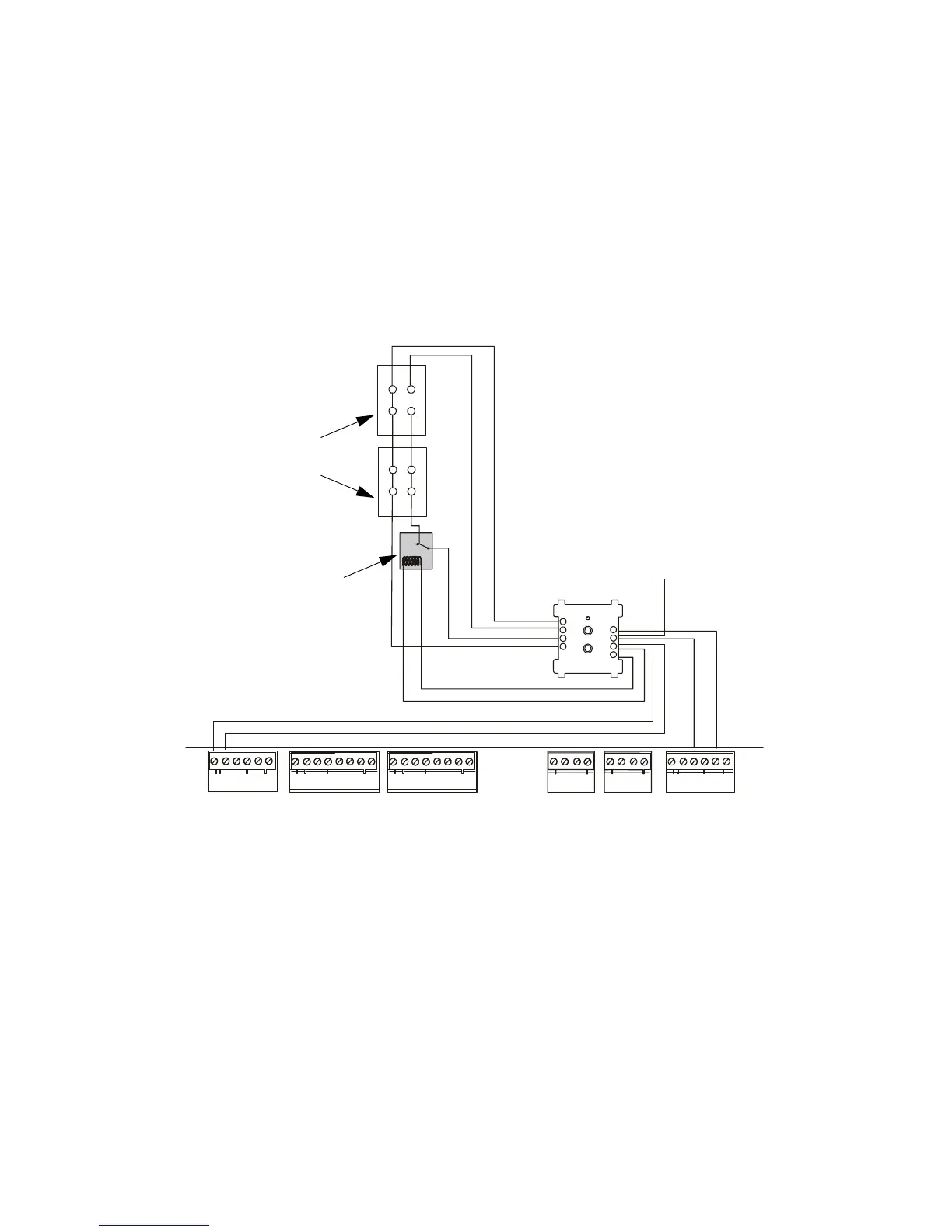
Style Z NAC
Figure 41 shows an NFPA Style Z NAC with notification appliances connected to a
control module.
Refer to the Device
Compatibility Document for
compatible notification
appliances.
Connect the NAC as follows:
1. Connect the SLC to control module terminals 1 (–) and 2 (+).
2. Connect 24 VDC power from TB1 to control module terminals 3 and 4.
3. Set the control module rotary switches to the required loop address. (The control
module takes one module address on the SLC.) Refer to 2.9.6 “Setting an SLC
Address for a Module” for instructions on addressing the modules.
Do not loop wiring under any terminals. Break wire run to maintain supervision. The
NAC is supervised and power-limited.
Figure 41 NFPA Style Z Notification Appliance Circuit
2.9.13 SLC Wiring with an Intelligent Detector
Overview for Wiring Intelligent Detectors
The B501 or B710LP base provides the connection between the SLC and the following
intelligent detectors: FSP-751, FSI-751, FST-751, and FST-751R.
1. Connect the communications loop to terminal 1 (–) and terminal 2 (+) on the
detector mounting base.
2. If using an RA400Z Remote LED Annunciator: (a) connect the RA400Z positive
terminal to base terminal 3; and (b) connect the RA400Z negative terminal to base
terminal 1.
TB4
TB5 TB6
TX REF RX REF
OUT OUT IN IN
1 2 3 4 5 6
A B B+ A+ B- A-
TB1
TB2 TB3
+ - + - + -
B+ B- B+ B- B+ B- B+ B- NO C NO NC C NO NC C
- +
90
81
72
63
54
-
-
+
+
+
+
-
-
+
+
-
-
UL-listed Power Supervision Relay
24 VDC
notification
appliances
To next device
on SLC
SLC out
SLC (+) to TB6-3
SLC (–) to TB6-5
24 VDC filtered, regulated, nonresettable
24 VDC (+) to TB1-1
24 VDC (–) to TB1-2
CPU
AFP200-NAC-Z-CMXa.cdr
Control
Module
Technical Manuals Online! - http://www.tech-man.com

 Loading...


