EasyManuals Logo

Notifier AFP-200 Installation Manual

Notifier AFP-200
196 pages
To Next Page IconTo Next Page
To Previous Page IconTo Previous Page
Page #58 background imageLoading...
Page #58 background image
Installation Wiring a Signaling Line Circuit (SLC)
58 AFP-200 PN 15511:H2 10/14/2002
Address for a Module” for instructions on addressing the modules.
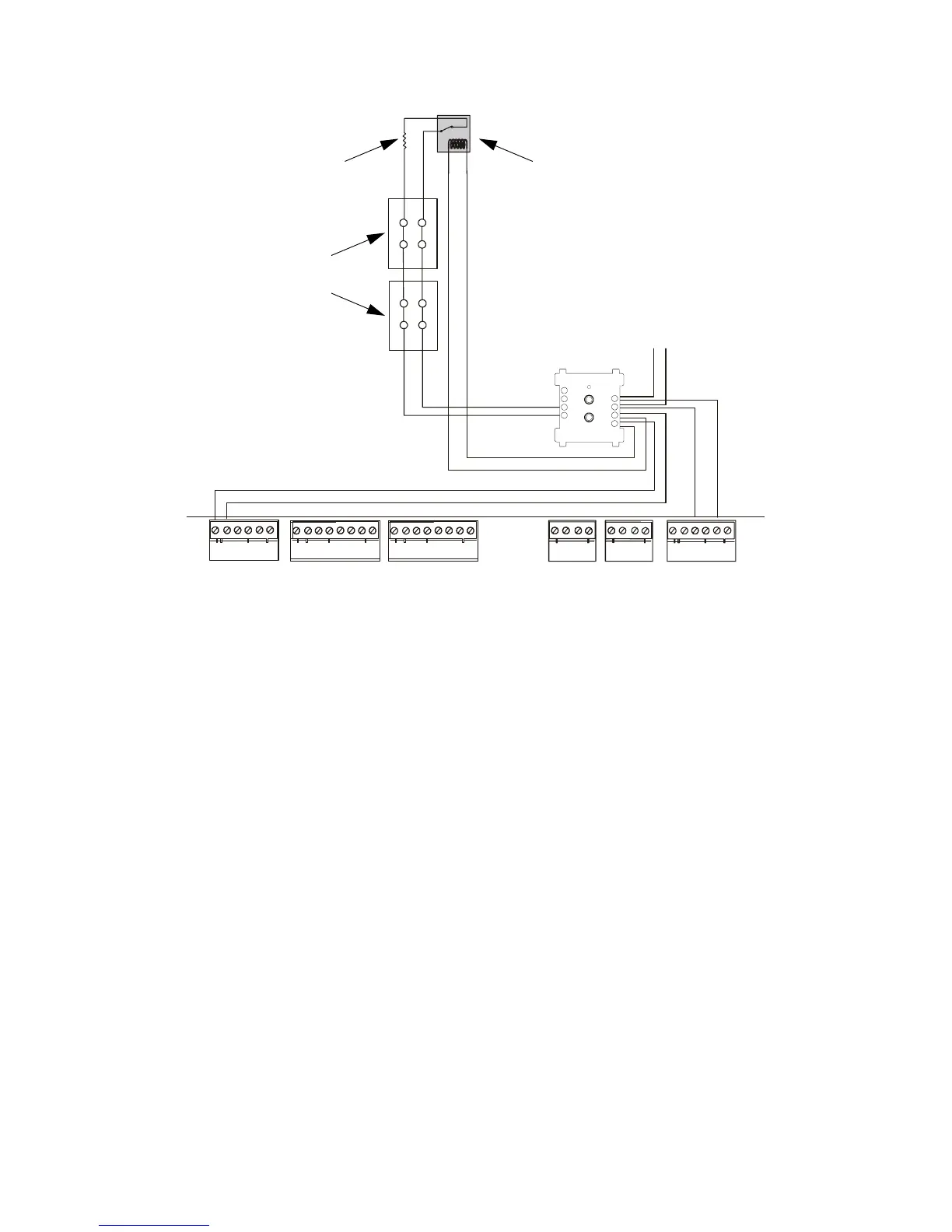
Figure 40 Typical Wiring for an NFPA Style Y NAC
- +
-
+
+
-
TB4
TB5 TB6
TX REF RX REF
OUT OUT IN IN
1 2 3 4 5 6
A B B+ A+ B- A-
TB1
TB2 TB3
+ - + - + -
B+ B- B+ B- B+ B- B+ B- NO C NO NC C NO NC C
90
81
72
63
54
-
+
+
+
-
-
+
+
-
-
UL-listed Power Supervision Relay
End-of-Line Resistor
47K, 1/2-watt
PN SSD A2143-00
(Use an N-ELR in Canada)
24 VDC
notification
appliances
To next device
on SLC
SLC out
SLC (+) to TB6-3
SLC (–) to TB6-5
24 VDC filtered, regulated, nonresettable
24 VDC (+) to TB1-1
24 VDC (–) to TB1-2
CPU
AFP200-NAC-Y-CMXa.cdr
Control
Module
Technical Manuals Online! - http://www.tech-man.com

Table of Contents

Other manuals for Notifier AFP-200

Questions and Answers:

Question and Answer IconNeed help?

Do you have a question about the Notifier AFP-200 and is the answer not in the manual?

Notifier AFP-200 Specifications

General IconGeneral
Control Panel TypeAddressable Fire Alarm Control Panel
Auxiliary Power Output24 VDC, 500 mA
Operating Temperature32°F to 120°F (0°C to 49°C)
Display80-character LCD
Power Supply120 VAC, 60 Hz
Capacity198 addressable devices
Notification Appliance Circuits2
Relay Contacts3 (Form-C)
Relative Humidity93% non-condensing

Related product manuals