Power Supply Calculations Calculating the System Current Draw
128 AFP-200 PN 15511:H2 10/14/2002
A.4 Calculating the System Current Draw
A.4.1 Overview
The control panel must be able to power all internal and external devices continuously
during the non-fire alarm condition. To calculate the non-fire alarm load on the system
power supply when primary power is applied, use Calculation Column 1 in Table 47.
The control panel must support a larger load current during a fire alarm condition. To
calculate the fire alarm load on the power supply, use Calculation Column 2 in Table
47. The secondary power source (batteries) must be able to power the system during a
primary power loss. To calculate the non-fire alarm load on the secondary power
source, use Calculation Column 3 in Table 47.
When calculating current draw and the battery size, note the following:
• “Primary” refers to the main power source for the control panel.
• “Secondary” refers to the control panel's backup batteries.
• All currents are given in amperes (A). Table 46 shows how to convert
milliamperes and microamperes to full amperes.
Table 46 Converting to Full Amperes
A.4.2 How to Use Table 47 to Calculate System Current
Draws
Use Table 47 to calculate current draws as follows.
1. Enter the quantity of devices in all three columns.
2. Enter the current draw where required. Refer to the Notifier Device Compatibility
Document for compatible devices and their current draw.
3. Calculate the current draws for each in all columns.
4. Sum the total current for each column.
5. Copy the totals from column 2 and column 3 to Table 48 on page 131.
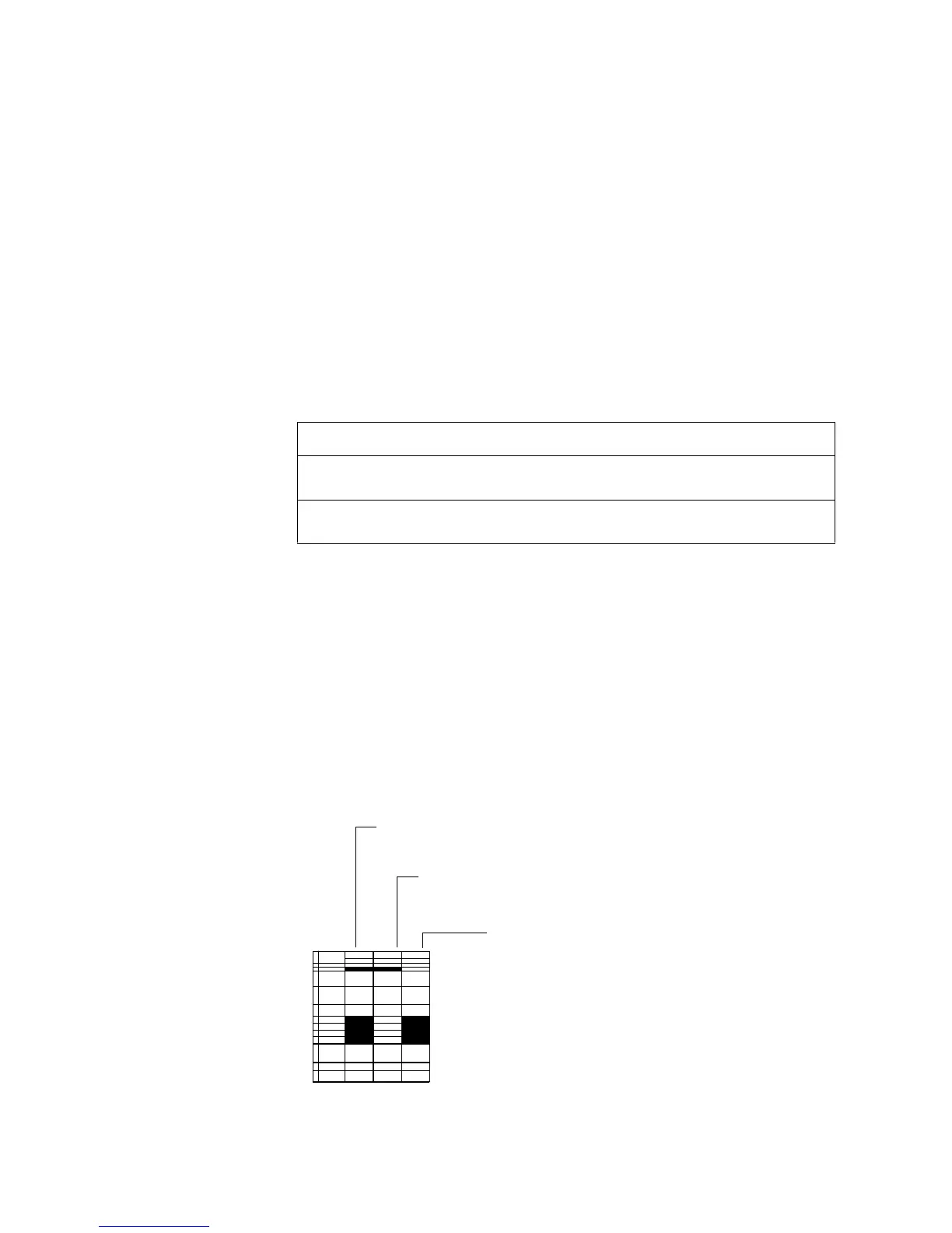
Figure 128 shows the types of current that you enter into Table 47:
Figure 128 Calculating the System Current Draws
To convert.... Multiply Example
Milliamperes (mA) to
amperes (A)
mA x 0.001 3 mA x 0.001= 0.003 A
Microamperes (µA) to
amperes (A)
µA x 0.000001 300 µA x 0.000001= 0.0003 A
Calculation Column 2 – The primary supply current load that the
control panel must support during a fire alarm condition, with AC
power applied. This current draw cannot exceed 5 A.
Calculation Column 1 – The primary supply current load that the control panel
must support during a non-fire alarm condition, with AC power applied. This current
draw cannot exceed 1.0 A.
Calculation Column 3 – the standby current drawn
from the batteries in a non-fire alarm condition during a
loss of AC power.
RowCategory
Calculation Colum n 1
Prim ary, N o n-Fire A larm
C alculation Col
Prim ary, Fire Al
(a m p s )
Calculat
Seco n da
QtyX [c u rre n t d ra w ]=to ta lQtyX [current d rawto ta lQtyX [currto ta
1Basic SystemN/AN/AN/AN/AN / A N / A1 x [0 .1 00.1
2AVPS-24
[ ]x [0.0 0
3 H ig h r ip p le p o w e r
TB1 term inals 1 and 2
N o tific a tio n a p p lia n c e s v ia C M X
N o tific a tio n a p p lia n c e s v ia C M X
R e leasin g d e vices via C M X
O t h e r c o m p a t ib le d e v ic e s
(N o t e 1 )
N/A
N/A
N/A
[ ]
N/A
N/A
N/A
x [ ]=
N/A
N/A
N/A
[ ]
[ ]
[ ]
[ ]
x [ ] =
x [ ] =
x [ ] =
x [ ] =
N/A
N/A
N/A
[ ]
N/A
N/A
N/A
x [
N/
N/
N/
4
Non-resettable power
TB1 term inals 3 and 4
AFM -16AT/A FM -32A Series
A C M -16 A T/A C M -3 2A Series
AEM -16AT/A EM -32A Series
AFM -16A
LC D -80, LC D -80TM (N ote 2)
A C M -8R (refer to D oc. 15342 )
LD M (refer to D oc. 15885)
UD ACT Com m unicator
O t h e r c o m p a t ib le d e v ic e s
[ ]
[ ]
[ ]
[ ]
[ ]
[ ]
[ ]
[ ]
[ ]
x [0.0 40]=
x [0.0 40]=
x [0.0 02]=
x [0.0 25]=
x [0.1 00]=
x [ ] =
x [ ] =
x [0.0 40]=
x [ ]=
[ ]
[ ]
[ ]
[ ]
[ ]
[ ]
[ ]
[ ]
[ ]
x [0.0 56]=
x [0.0 56]=
x [0.0 18]=
x [0.0 65]=
x [0.1 00]=
x [ ]=
x [ ]=
x [0.1 00]=
x [ ]=
[ ]
[ ]
[ ]
[ ]
[ ]
[ ]
[ ]
[ ]
[ ]
x [0.0 4
x [0.0 4
x [0.0 0
x [0.0 2
x [0.0 5
x [
x [
x [0.0 4
x [
5Resettable Power
Four-w ire sm oke detector
Tw o-w ire sm oke detector
c o n n e c t e d t o M M X -2
A 77-71 6B Relay
O th er co m p a tib le d e vice s
(N o t e 1 )
[ ]
[ ]
[ ]
[ ]
x [ ] =
x [ ] =
x [0 .020]=
x [ ] =
[ ]
[ ]
[ ]
[ ]
x [ ] =
x [ ] =
x [0.0 20]=
x [ ] =
[ ]
[ ]
[ ]
[ ]
x [
x [
x [0.0 2
x [
6NAC #1 (Note 1)
TB2 term inals 1 and 2
N o tific a tio n A p p lia n c e
R e le a s in g S o le n o id
[ ]
[ ]
x [ ]=
x [ ]=
7NAC #2 (Note 1)
TB2 term inals 3 and 4
N o tific a tio n A p p lia n c e
R e le a s i n g S o le n o id
[ ]
[ ]
x [ ]=
x [ ]=
8 N A C # 3 (N otes 1 an d 3) TB2 ter
6
N o tific a tio n A p p lia n c e
R e le a s in g S o le n o id
[ ]
[ ]
x [ ]=
x [ ]=
9 N A C # 4 (N o t e s 1 a n d 3 )
TB2 term inals 7 and 8
N o tific a tio n A p p lia n c e
R e le a s in g S o le n o id
[ ]
[ ]
x [ ]=
x [ ]=
10SLC C om m unication Loop
TB6 term inals 3–6
SD X-5 51 , C PX -5 51, C PX-75 1
& FD X-551, SD X-551 TH
SD X -7 5 1
M M X-1, M M X-101, BG X-10 1L
CM X
MMX-2 (see Doc. M500-03-00)
B6 0 1 BH
B5 0 1 BH (H o rn in b ase )
D H X-50 1, D H X-502 (see data sh
IS O - X
[ ]
[ ]
[ ]
[ ]
[ ]
[ ]
[ ]
[ ]
[ ]
x [0 .0002 0]=
x [0 .0002 9=
x [0 .0003 0]=
x [0 .0003 0]=
x [ ]=
x [0 .0010 0]=
x [0 .0010 0]=
x [ ]=
x [0 .0004 5]=
[ ]
[ ]
[ ]
[ ]
[ ]
[ ]
[ ]
[ ]
[ ]
x [0.0 002 0]=
x [0.0 002 9]=
x [0.0 004 3]=
x [0.0 003 0]=
x [ ]=
x [0.0 010 0]=
x [0.0 150 0]=
x [ ]=
x [0.0 004 5]=
[ ]
[ ]
[ ]
[ ]
[ ]
[ ]
[ ]
[ ]
[ ]
x [0.0 0
x [0.0 0
x [0.0 0
x [0.0 0
x [
x [0.0 0
x [0.0 0
x [
x [0.0 0
11O ptional m odu les
R T M -8 (N o t e 4 )
4XTM
M unicipal Box (N ote 5)
R e v e rs e P o la rity O u tp u ts u s e d
[ ]
[ ]
[ ]
x [ 0.0010]=
x [ 0.0110]=
N/A
x [ 0.0050]=
[ ]
[ ]
[ ]
[ ]
x [ 0.160]=
x [ 0.020]=
x [ ] =
x [ 0.0050]=
[ ]
[ ]
[ ]
x [ 0.0
x [ 0.0
N/A
x [ 0.0
12Sum each column for totals
Prim ary non-alarm :
(1 .0 A m a x .):
Prim ary alarm
(5 .0 A m a x ) :
Copy to Table A-
A larm Lo ad "
Seco n da
Copy to
"S e c o n d

 Loading...


