NFPA 72 Auxiliary Fire Alarm System NFPA Applications
AFP-200 PN 15511:H2 10/14/2002 135
to 2 (refer to the UDACT manual)?
5. Is the ACS/ TERM switch (SW2) on the control panel set to the ACS position?
6. Is the control panel programmed for “ANNUN=UDACT”?
7. Is the control panel configured for proper supervision? Supervise the UDACT via
the COMM FAIL output (refer to Monitoring for UDACT Trouble in the UDACT
Manual)?
• For a system without an annunciator – configure the UDACT for
Receive/Transmit.
• For a system with an annunciator – configure the UDACT for Receive Only and
the annunciator for Receive/Transmit.
Note: If the annunciator does not require remote control capabilities (Reset,
Acknowledge, Silence, etc.), 'COMM FAIL' monitoring is not required if the following
conditions are met: the UDACT is configured for “Receive/Transmit” and the
annunciator is configured for “Receive Only”.
B.3 NFPA 72 Auxiliary Fire Alarm System
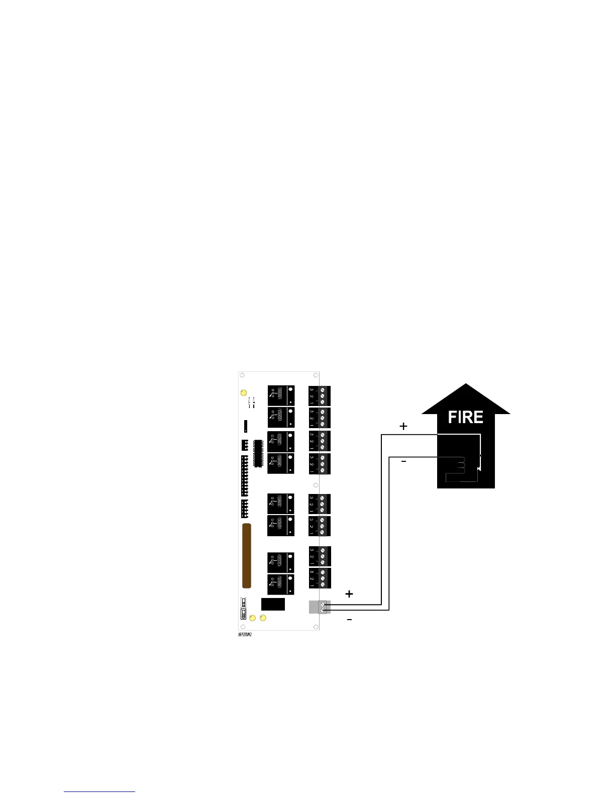
Figure 131 and 131 show typical connections (all connections are nonpower-limited
and supervised) for wiring the control panel to a municipal box. Maximum loop
resistance allowed for wiring from control panel to Municipal Box is 5 ohms. Cut JP5
on control panel circuit board. This application is not suitable for separate transmission
of sprinkler supervisory or trouble conditions.
Figure 131 Wiring a Municipal Box Connected to a RTM-8
Gamewell Model M34-56
Local Energy Municipal Box
Municipal Box Circuit
Polarities shown in
alarm condition
Jumper JP2 must be in
the LE MUNCPL BOX
position for use in this
application
RTM-8 Module
Technical Manuals Online! - http://www.tech-man.com
 Loading...


