Annunciators Terminal Mode EIA-485 Connections (TB5)
144 AFP-200 PN 15511:H2 10/14/2002
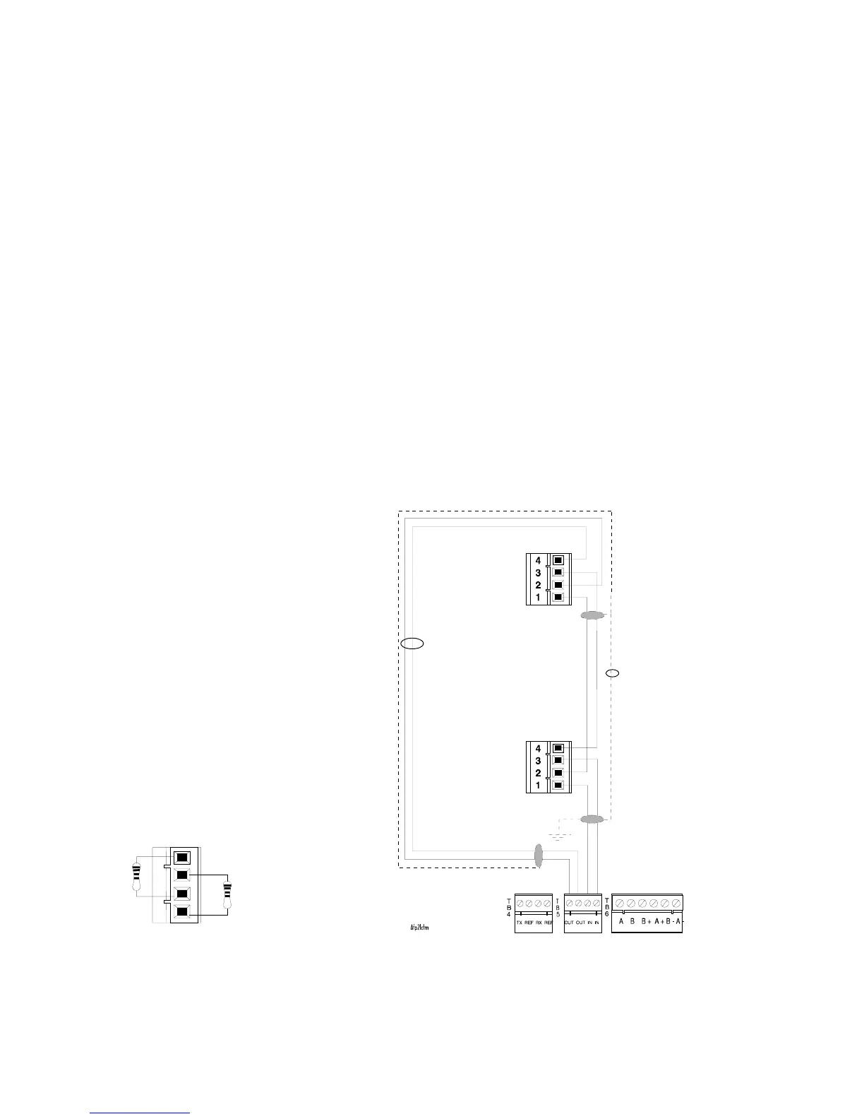
C.5 Terminal Mode EIA-485 Connections (TB5)
Refer to the LCD-80 Manual
for additional information.
This section shows how to install LCD-80s set for Terminal Mode to the control panel,
subject to the following:
• Maximum number of LCD-80s allowed – A maximum of four LCD-80s may be
connected when powered by the control panel. If, however, the LCD-80s are
powered by a separate UL-listed power supply, up to 32 may be connected.
• Maximum distance – There is a 6,000 foot (1828.8 m) maximum distance (16
AWG) between the control panel and the first or last LCD-80 and between each
LCD-80.
• Cable – Use overall foil/braided-shield twisted-pair cable suitable for EIA-485
applications.
• Circuit rating – The EIA-485 circuit is rated 5.5 VDC max., 60 mA max. For
non-English language systems, LCD-80 standby current is the same as the alarm
current (100 mA).
Connect the EIA-485 circuit as follows:
1. Connect each LCD-80 to 24 VDC operating power (power-limited and supervised)
to the AFP-200 as shown in Figure 139 on page 146.
2. Set SW2 on the control panel to the TERM position (left position).
3. Set SW4 and SW5 on the LCD-80 to the TERM position: SW1-7 ON.
4. Install R-120 resistors across the in and out terminals of each LCD-80 as shown in
Figure 136.
Figure 136 Terminal Mode EIA-485 Connection
TB5-1 (+)
TB5-2 (–)
shielded twisted
Out (+)
first LCD-80
EIA-485 out
EIA-485 return
EIA-485 In (–)
EIA-485 Out (–)
EIA-485 In (+)
EIA-485 Out (+)
EIA-485 In (–)
EIA-485 Out (–)
EIA-485 In (+)
EIA-485 Out (+)
Last LCD-80 – SW3-1 and
SW3-2 must be set ON on the
last LCD-80.
First LCD-80 – must set DIP
Switch SW3-1 AND SW3-2 “OFF”
on all LCD-80s except the last one.
last LCD-80
P2
P2
r-120lcd.wmf
Install R-120 resistors across the in
and out terminals of each LCD-80
Technical Manuals Online! - http://www.tech-man.com

 Loading...


