16
Nomenclature Section 2-1
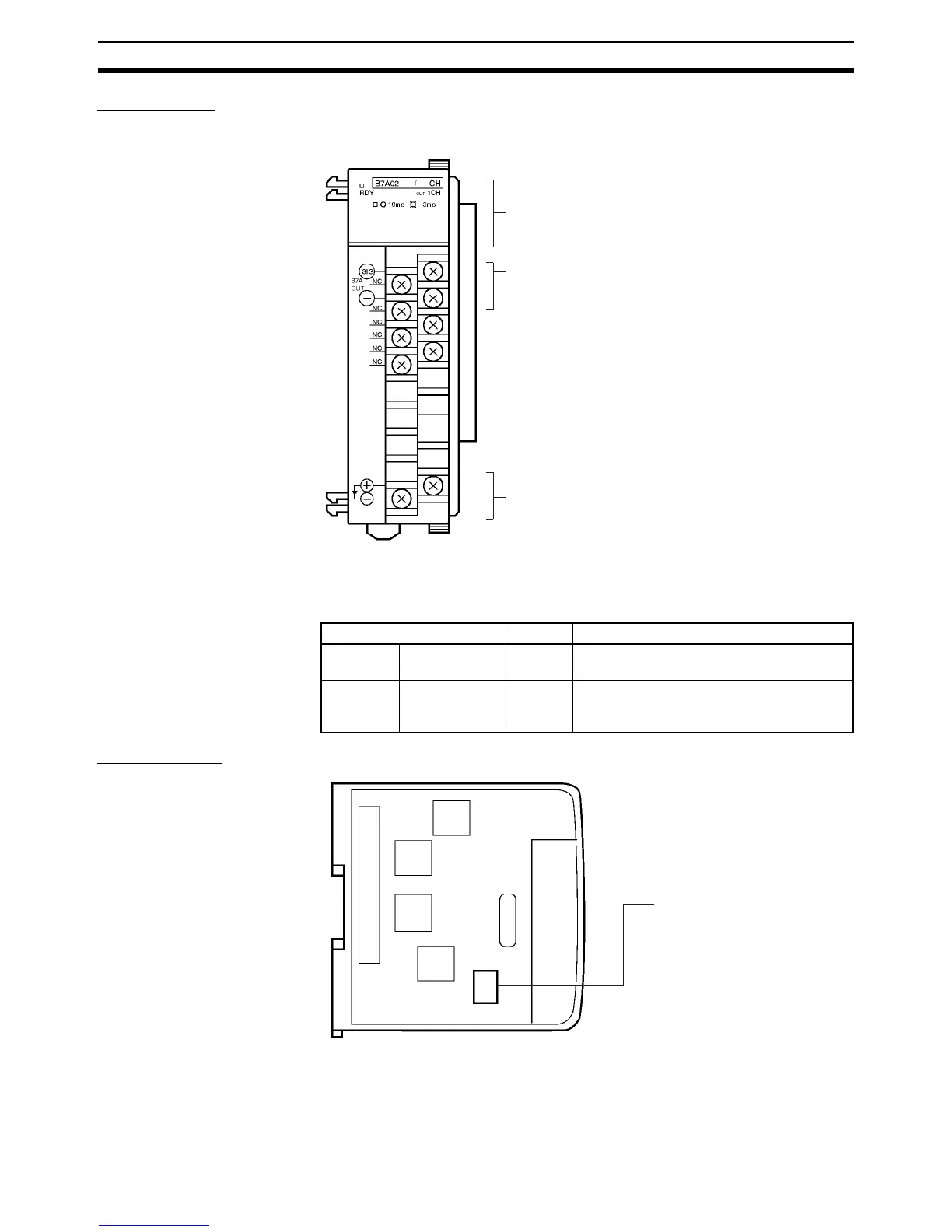
CQM1-B7A02
Front View
Indicators
Left-side View Common to all models.
Indicators (see following table)
B7A Link Terminal connection terminals 1
For connection of a 16-point output B7A Link Terminal.
External power terminals
Required for transmission with the B7A Link Terminal. Con-
nect a 12- to 24-VDC power supply.
Terminal screws: M3
(Optimum tightening torque: 0.5 N • m)
Name Color Function
RDY Unit ready Green Lit while the CQM1H/CQM1 is supplied with
power.
19ms/3ms Transmission
delay time
Orange Lit while transmission delay time is set to
RAPID (3 ms). Not lit when set to STAN-
DARD (19.2 ms).
Operation setting DIP Switch
Sets to the operation of the
B7A Interface Unit (see page
15). Set the switches before
mounting the B7A Interface
Unit in CQM1H/CQM1. To set
after mounting, remove the ter-
minal block and make the set-
ting from the front face.