23
Wiring Section 3-2
3. Locate transmission cables away from power cables and high-voltage ca-
bles to eliminate the effects of noise.
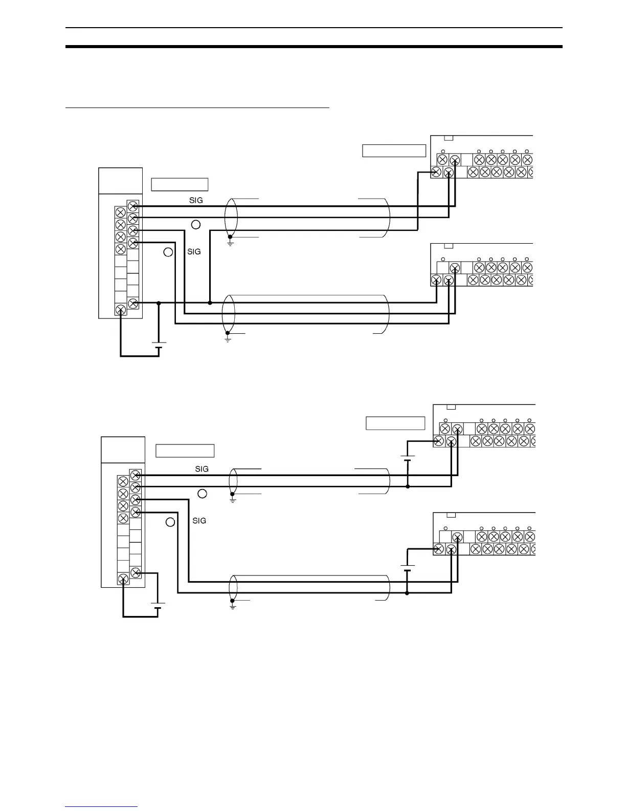
Rapid Transmission Delay-time Link Terminal
Single Power Supply
Independent Power Supplies
Note 1. The transmission distance depends on the type of wiring used.
2. The size of terminal screw differs for the B7A Interface Unit and B7A Link
Terminal. Consider the size of the terminal screws when using crimped ter-
minals.
3. It is recommend that the shield wire be grounded.
B7A Interface Unit
B7A Link Terminal
+
12 to 24 VDC
–
Transmission distance:
50 m max.
Transmission cable:
shielded, 0.75 mm
2
min.
B7A Link Terminal
Terminal screws: M3
Terminal screws: M3.5
–
Shielded cable:
0.75 mm
2
min.
Ground
Ground
Terminal screws: M3
Terminal screws: M3.5
B7A Interface Unit
B7A Link Terminal
+
12 to 24 VDC
–
Transmission distance:
50 m max.
Transmission cable:
shielded, 0.75 mm
2
min.
B7A Link Terminal
–
Shielded cable:
0.75 mm
2
min.
Ground
Ground
+
+
12 to 24 VDC
12 to 24 VDC