33
System Configuration Section 1-2
Configuration as Multiple Systems
Note 1. When multiple Masters are used, allocate system numbers to them in se-
quence from 1, starting from the Master nearest the CPU. The system
numbers have no special significance. Refer to 4-1 Word Allocation.
2. Up to two Expansion Masters can be connected to each Master.
3. When two Expansion Masters are used, set one as Unit 1 and the other as
Unit 2. The Slave address for Unit 2 can only be used for an 8-point or 16-
point Slave. It cannot be used for a 4-point Slave.
4. Masters and Expansion Masters can be used in any combination, provided
that the maximum number of input and output points remains within the
range permitted for the CPU.
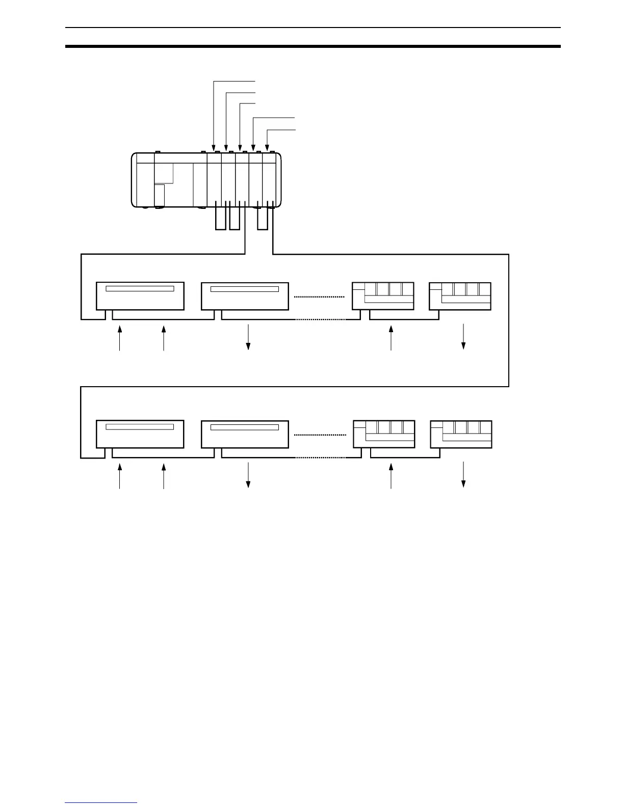
Master, System 1 (32 input points/32 output points max.)
Expansion Master Unit 1 (max. 32 input points or 32 output points)
Expansion Master Unit 2 (max. 32 input points or 32 output points)
Master, System 2 (32 input points/32 output points max.)
Expansion Master Unit 1 (max. 32 input points or 32 output points)
RS-485, 200 m max.
G730-VI (input model) G730-VO (output model) G730-RI (input model)
G730-RO (output model)
Switch Sensor Lamp ValveSwitch
G730-VI (input model) G730-VO (output model) G730-RI (input model) G730-RO (output model)
Switch Sensor Lamp ValveSwitch