7.2 Calibrating Thermocouple
E5EK
7--5
This example describes how to calibrate a thermocouple when the
transfer output function is supported. If the transfer output function is
not supported, skips steps (7) to (10).
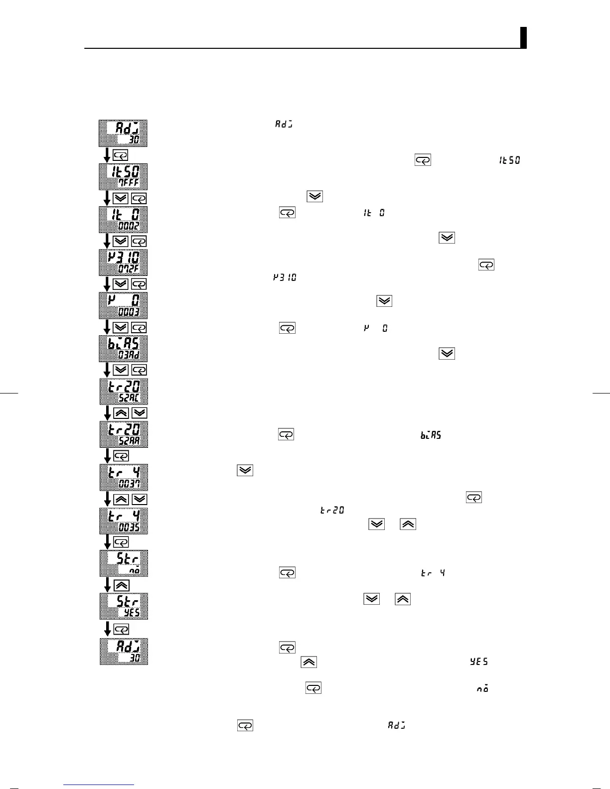
(1) When [
] is displayed, the 30 -minute timer is displayed on the
No.2 display and counts down. This timer serves as a guide for the
aging time when agin g is required.
(2) First, calibrate the main input. Press the
key to display [ ]
(50mV calibration disp lay). Set STV output to 50mV. When the
value on the No.2 display has stabilized (changes of several digits
max.), press the
key to temporarily save the calibration data.
(3) Pr ess the
key to display [ ] (0mV calibration display). Set
STVoutputto0mV.WhenthevalueontheNo.2displayhasstabi-
lized (changes of several digits max.), p ress the
key to tempo-
rarily save the calibration data.
(4) Next, calibrate the cold junction compensator. Press the key to
display [
] (310mV cali bration display). Set STV output to
310mV. When the value on the No.2 display has stabilized (changes
of several digits max.), press the
key to temporarily save the
calibration data.
(5) Pr ess the key to display [ ] (0mV calibration display). Set
STVoutputto0mV.WhenthevalueontheNo.2displayhasstabi-
lized (changes of several digits max.), p ress the
key to tempo-
rarily save the calibration data.
(6) Finally, calibrate the bias compensation value. Disconnect the STV,
and enable the thermocouple of the cold junction compensator.
When carrying this out, make sure that the wiring on the STV is
disconnected.
Make sure that the cold junction compensator is set to 0_Cand
press the
key. The display changes to [ ] (calibration dis-
play for the bias compensation value). When the value on the No.2
display has stabilized (changes of several digits max.), press the
key to temporarily save the calibration data.
(7) Next, calibrate the transfer output function. If the transfer output
function is not supported, skip to step (11). Press the
key. The
display changes to [
] (20mA calibration display).
(8) Set the o utput to 20mA by the
or keys while monitoring
the voltage on the digital multimeter. In the example on the left,
the display indicates that the value two digits smaller than before
calibration is “20mA”.
(9) Pr ess the
key. The display changes to [ ] (4mA calibration
display).
(10) Set the output to 4mA by the
or keys while monitoring the
voltage on the digital multimeter. In the example on the left, the
display indicates that the value two digits smaller than before cal-
ibration is “4mA”.
(11) Press the
key until the display changes to the data save dis-
play. Press the
key. The No.2 display changes to [ ], an d
two seconds later the calibration data is saved to internal memory.
If you press the
key when the No.2 display reads [ ], the
calibration data is invalidated.
(12)This completes calibration of the thermocouple 1 group. Press the
keytoreturnthedisplayto[ ].
F Calibration:
thermocouple 1