APPENDIX
E5EK
A-- 12
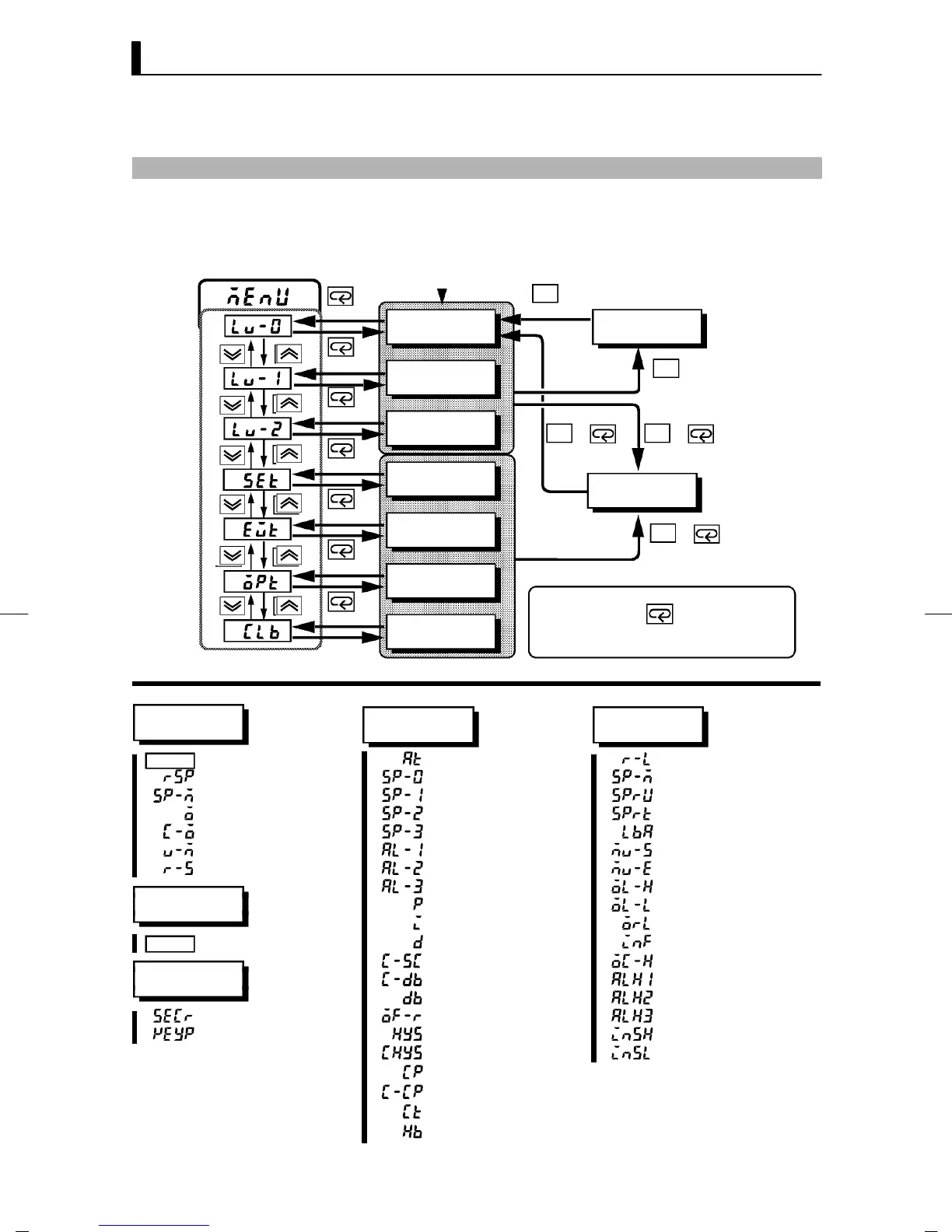
PARAMETER OPERATIONS LIST
• Switching to modes other than manual or protect mode is carried out by mode selection in the
menu display.
• The figure below shows all parameters in the order that they are displayed. Some parameters are
not displayed depending on the protect mode setting and conditions of use.
A/M
A/M
A/M
A/M
A/M
++
+
1 second min.
Level 0 mode
Level 1 mode
Level 2 mode
Setup mode
Expansion
mode
Option mode
Calibration
mode
1secondmin.
Manual mode
Protect mode
1 second min.
1 second min. 1 second min.
1secondmin.
Parameters in a mode can be
switched by the key. The param-
eter following the last parameter is the
top parameter.
1 second min.
Power ON
1 second min.
1 second min.
1 second min.
1 second min.
1 second min.
Level 0
Level 1
Level 2
PV/SP AT Execute/Cancel Remote/Local
Remote SP monitor Set point 0 SP mode
Set point during SP ramp Set point 1 SP ramp time unit
MV monitor (heat) Set point 2 SP ramp set value
MV monitor (cool) Set point 3 LBA detection time
Valve opening monitor Alarm value 1 MV at stop
Run/Stop Alarm value 2 MV at PV error
Alarm value 3 MV upper limit
Manual mode
Proportional band MV lower limit
Integral time MV change rate limit
Manual MV Derivative time Input digital filter
Cooling coefficient Open/close hysteresis
Protect mode
Dead band Alarm 1 hysteresis
Position--proportional dead band Alarm 2 hysteresis
Security Manual reset value Alarm 3 hysteresis
[A/M] key protect Hysteresis (heat) Input shift upper limit
Hysteresis (cool) Input shift lower limit
Control period (heat)
Control period (cool)
Heater current monitor
Heater burnout