CHAPTER 7 CALIBRATION
E5EK
7--2
7.1 Structure of Parameters
• To calibrate the E5EK controller, select [ ]inthe menudisplay
to select the calibration mode. [
]isdisplayed.
• However, note that [
] may not be displayed on the menu display
when, for example, the user is calibrating the E5EK controller for the
first time. If this happens, [
] is displayed by changing the “secu-
rity” p arameter (pr otect mode) to “0”.
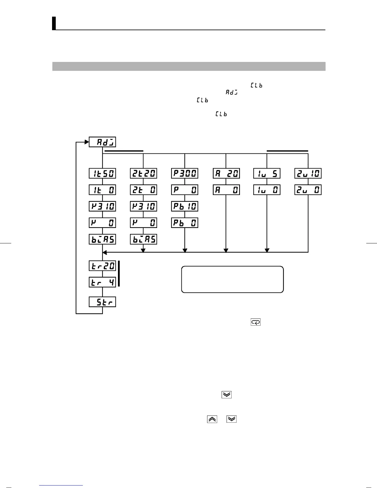
• The parameters in the calibration mode are configured as follows.
0to10V0to5V 1to5V
Thermocouple
Thermocouple 1
Transfer output
Data save
Platinum resistance
thermometer
Voltage inputCurrent input
Thermocouple 2
Thermocouple 1 : K1/J1/L1/E/N/W/PLII
Thermocouple 2 : K2/J2/L2/R/S/B/T/U
Platinum resis tance
thermometer : JPt100/Pt100
Only when transfer
output function is
supported
• To select the desired parameter, press the key. Parameters are
displayed in the following order:
Calibration of inputs → Calibration of transfer output →
Saving of calibration data
If the E5EK controller does not support the transfer output function,
calibration of transfer output is automatically deleted from the cal -
ibration procedure as follows:
Calibration of inputs → Saving of calibration data
• Only inputs that have been set in the “input type” parameter (setup
mode) can be calibrated. To temporarily save data for each of the cal-
ibration parameters, press the
key for 1 second.
• Transfer output can b e calibrated only when the communications
unit (E53-AKF) is set in the controller. To ad-
just data items, press the
or keys.
• The data save menu is displayed only when all calibration items have
temporarily been saved.
• After calibrating input, you must always check indication accuracy.
For details, see page 7-12.