CHAPTER 2 PREPARATIONS
E5EK
2--8
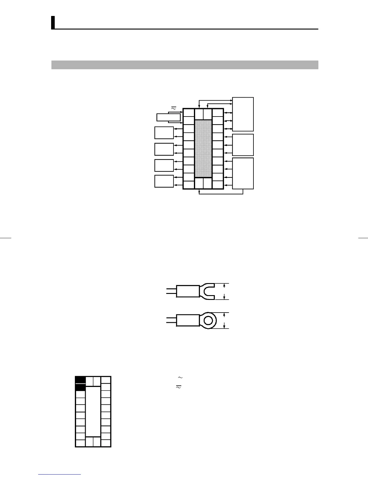
2.3 Wiring Terminals
JTerminal arrangement
10
OUT1
OUT2
SUB1
SUB2
9
8
7
6
5
4
3
2
1
20
19
18
17
16
15
14
13
12
11
21 22
23
EV1/2
TRSF
RS232C
RS422
RS485
RSP
CT
PTMR
TC
Pt
I
V
TRSF : Transfer output
EV1/2 : Event inputs
PTMR : Potentiometer
SOURCE
AC100-240V
(AC/DC24V )
~
• Use ducts to separate input leads and power lines in order to protect
the controller and its lines from external noise.
• We recommend using solderless terminals when wiring the controller.
• Tighten the terminal screws using a torque no greater than 0.78 N·m,
or 8 kgf·cm max. Take care not to tighten the terminal screws too
tightly.
• Use the following type of solderless terminals for M3.5 screws.
7.2mm max.
7.2mm max.
In the following wiring diagrams, the left side of the terminal Nos. indi-
cates the inside of the controller
• Input power to term inal Nos . 9 a nd 10. P owe r spe cificat ions are as fol-
lows :
AC100-240V
, 50/60Hz, 15VA
(AC/DC24V
, 50/60Hz, 12VA 8W)
JPrecautions
when wiring
JWiring
F Power supply
10
9
8
7
6
5
4
3
2
1
20
19
18
17
16
15
14
13
12
11
21 22
23