CHAPTER 1 INTRODUCTION
E5EK
1--8
set the communications conditions, transfer output and event input
parameters to match the type of option unit set in the controller. Heater
burnout latch function, position-proportional travel time and remote
SP scaling parameters are also located in this mode.
This mode is provided so that the user can calibrate inputs and transfer
output.
When calibrating input, the selected input type is calibrated. Whereas,
transfer output can be calibrated only when the communications unit
(E53-AKF) is set in the controller.
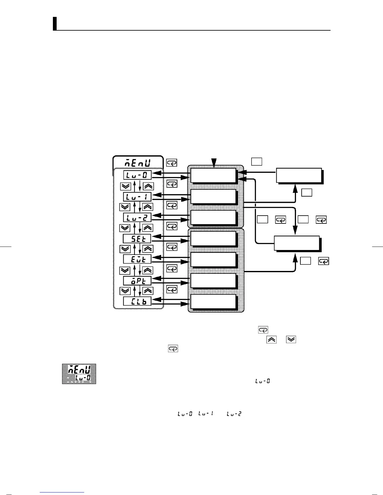
The following diagram shows the order in which modes are selected.
A/M
A/M
A/M
A/M
A/M
++
+
1 second min.
Level 0 mode
Level 1 mode
Level 2 mode
Setup mode
Expansion mode
Option mode
Calibration mode
1secondmin.
Manual mode
1secondmin.
1 second min. 1 second min.
Protect mode
1secondmin.
1 second min.
Power ON
1 second min.
1 second min.
1 second min.
1 second min.
1 second min.
• To select the menu display in any of the above modes (excluding the
protect mode and manual mode), press the
key for 1 second mini-
mum. If you select the desired mode using the
or keys and
press the
key, the top parameter in the specified mode is dis-
played.
• When you have selected the menu display, the previous mode is
selected. For example, if you selected the menu display while in the
level 0 mode, the No.2 display changes to [
] as shown on the left.
• Protected modes cannot be selected. Also, the menu display does not
appear when modes are protected up to the level 1 mode.
• If you select [
][ ]or[ ] in the menu display, the level 0,
level 1 and level 2 modes, respectively, are selected.
• These modes are selected with control still continuing.
F Calibration mode
JSelecting modes
F Menu display
F Level 0 to 2
modes