CHAPTER 7 CALIBRATION
E5EK
7--10
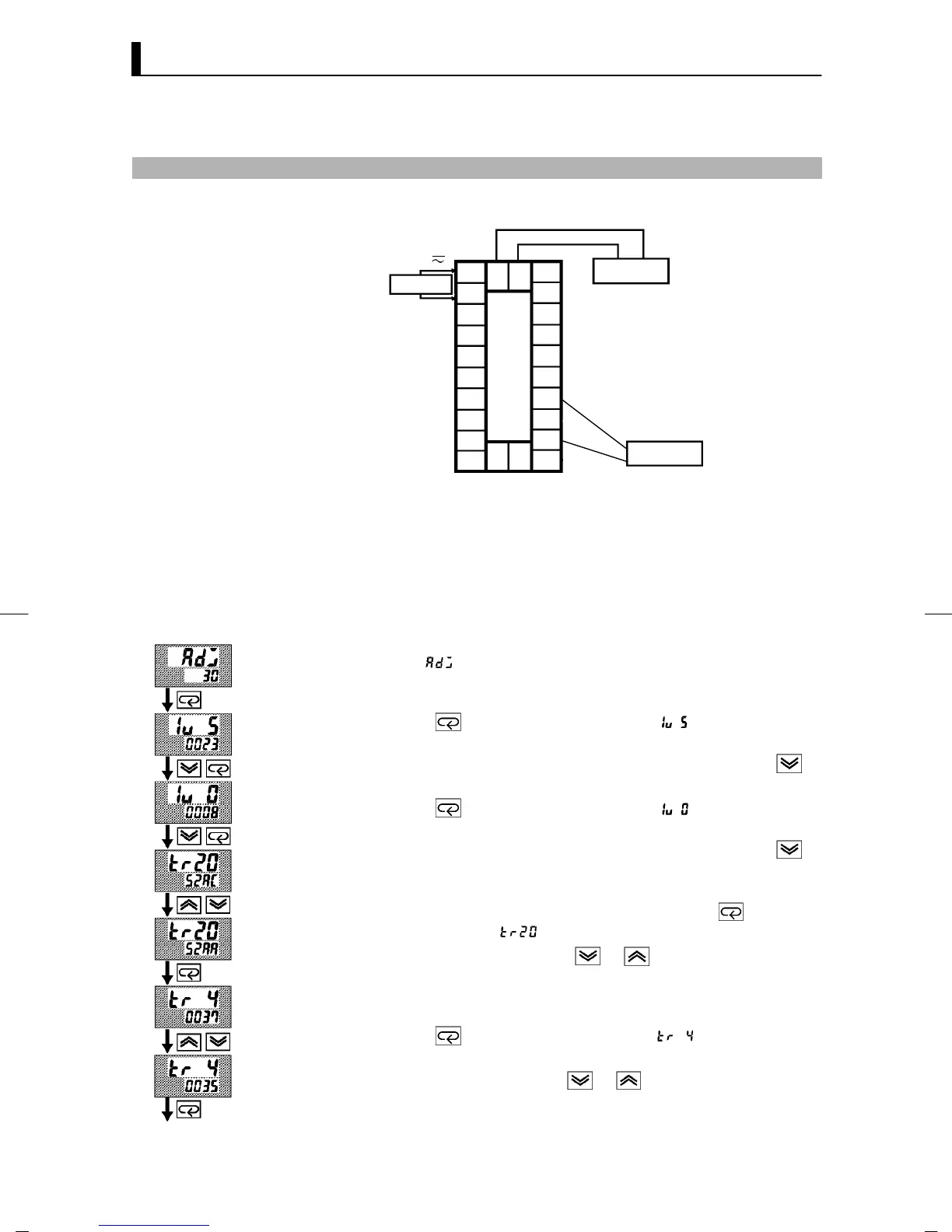
7.5 Calibrating Voltage Input
F Preparation
10
9
8
7
6
5
4
3
2
1
20
19
18
17
16
15
14
13
12
11
21 22
23
DMM
STV
+
--
SOURCE
AC100-240V
(AC/DC24V )
~
• In the above figure, STV refers to a standard DC current/voltage
source, and DMM refers to a precision digital multimeter. However,
note that the DMM is required only when the transfer output func-
tion is supported.
This example describes how to calibrate voltage input when the trans-
fer output function is supported. If the transfer output function is not
supported, skips steps (4) to (7).
(1) When [
] is displayed, the 30 -minute timer is displayed on the
No.2 display and counts down. This timer serves as a guide for the
aging time when agin g is required.
(2) Pr ess the
key. The display changes to [ ] (5 V calibration
display). Set the STV output to 5V. When the value on the No.2 dis-
play has stabilized (changes of several digits max.), press the
key to temporarily store the calibration data.
(3) Pr ess the
key. The display changes to [ ] (0V calibration
display). Set the STV output to 0V. When the value on the No.2 dis-
play has stabilized (changes of several digits max.), press the
key to temporarily store the calibration data.
(4) Next, calibrate the transfer output function. If the transfer output
function is not supported, skip to step (8). Press the
key. The
display changes to [
] (20mA calibration display).
(5) Set the o utput to 20mA by the
or keys while monitoring
the voltage on the digital multimeter. In the example on the left,
the display indicates that the value two digits smaller than before
calibration is “20mA”.
(6) Pr ess the
key. The display changes to [ ] (4mA calibration
display).
(7) Set the output to 4mA by the
or keys while monitoring the
voltage on the digital multimeter. In the example on the left, the
display indicates that the value two digits smaller than before cal-
ibration is “4mA”.
F Calibration:
0to5V,1to5V
Cont’d on next page