CHAPTER 5 PARAMETERS
E5EK
5--6
• The parameters in this mode can be used only when the “security” parameter
(protect mode) is set to “0” to “4”.
• The “PV/SP” parameter can be used when the “security” parameter is set to “5”
or “6”. However, note that the SP cannot be changed when it is set to “6”.
• This mode is used for monitoring the process value, set point and manipulated
variable during operation, and for checking and setting the SP setting value. It is
also used for starting and stopping controller operation.
• To select this mode when in the levels 1 and 2, setup, expansion, option and cal -
ibration modes, press the
key for 1 second minimum. The display changes to
the menu display. If you select [
]thenpress key for 1 second minimum,
the controller enters the level 0 mode.
• To select parameters in this mode, press the
key. To change parameter set-
tings, use the
or keys.
• The following table shows the parameters supported in this mode and the page
where the parameter is described.
Symbol
Paramete r Name
Page
PV/SP 5-6
Remote SP monitor 5-7
Set point during SP ramp 5-8
MV monitor (heat) 5-8
MV monitor (cool) 5-8
Valve opening monitor 5-9
Run/Stop 5-9
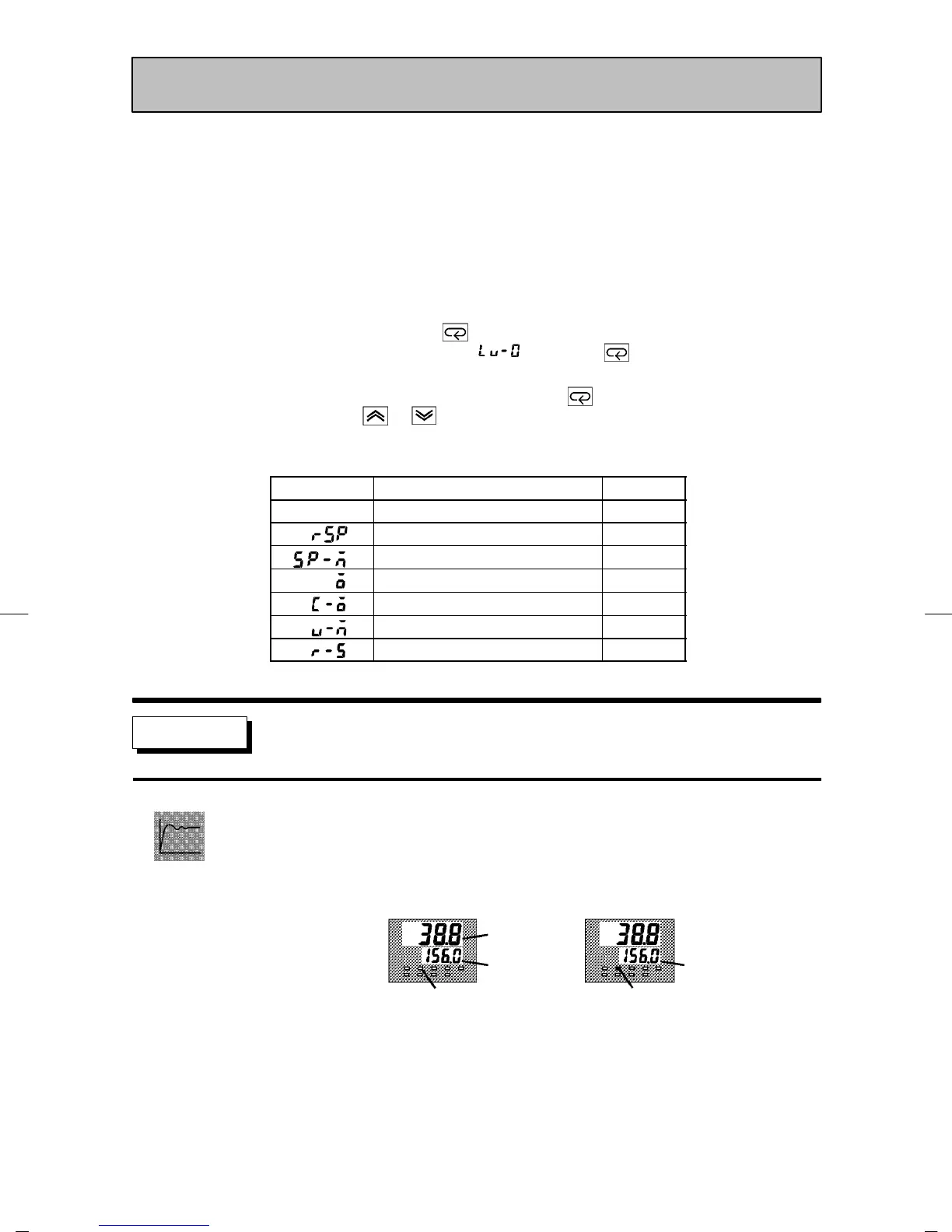
PV/SP
• The process value is displayed on the No.1 display, and the set point is displayed
on the No.2 display. The set point can be set.
• Either of the local SP or remote SP is displayed as the set point depending on the
SP mode. In the remote SP mode, the set p oint is only monitored.
Process value
Set point
[RSP] LED not lit
Monitor only
[RSP] LED lit
Local SP mode Remote SP mode
• The selected set point is linked when the multi-SP function is in use in the local
SP mode. For example, when set point 1 is selected, set point 1 is displayed o n the
No.2 display, and the setting of the “set point 1” parameter (level 1 mode) also is
changed when the value o f set point 1 is changed.
• The decimal point position is dependent on the selected sensor during tempera-
ture input and on the results of scaling during analog input.
Level 0 Mode
Function