6.2 Preparing for Communications
E5EK
6--3
6.2 Preparing for Communications
For details on wiring when using the communications, see Chapter 2
Preparations.
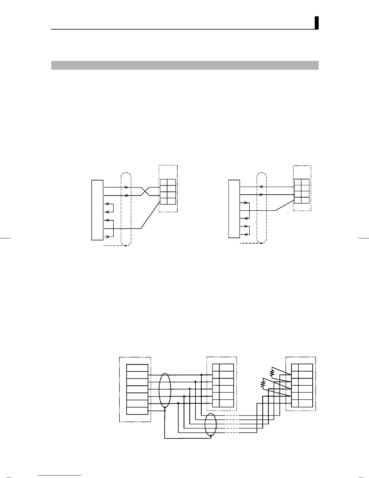
JCable connections
• Only one controller can be connected to the host computer.
• The cable length should not exceed 15 meters.
• Use shielded twisted-pair cables (AWG28 or more) for the cables.
RS-232C
No.
20
SD
RD19
18 SG
E5EK
RS-232C
No.
20
SD
RD19
18 SG
E5EK
IBM-PC/XT
DE-25
Female
DTE
(SD) TXD
(RD) RXD
(RS) RTS
(CS) CTS
(SG) COMMON
(ER) DTR
(DR) DSR
2
3
4
5
20
6
7
FG 1
(RD) RXD
(SD) TXD
(ER) DTR
(SG) COMMON
(RS) RTS
(CS) CTS
(DR) DSR
2
3
4
5
8
6
7
FG 1
25 pins
IBM-PC/AT
DE-25
Female
DTE
9pins
• Up to 32 controllers including a computer can be connected to the
host computer.
• The total cable length should not exceed 500 meters.
• Use shielded twisted-pair cables (AWG28 or more) for the cables.
• Attach terminators to the controllers at both ends of a series of con-
trollers connected in an open configuration. For example, in the fol-
lowing configuration, connect the terminator to the host unit and
unit No.30, and do not connect terminators to unit Nos.0 to 29.
• Use terminators having a resistance of 240 Ω (1/2 W). The total resis-
tance of both ends should be at least 100 Ω.
Host computer E5EK (No.0) E5EK (No.30)
RS-422 RS-422 RS-422
Shielded cable
TerminatorX2
(240 Ω 1/2 W)
RDA
RDB
SDA
SDB
SG
FG
SDA
22
No.
SDB
21
RDA
19
RDB
20
SG
18
SDA
22
No.
SDB
21
RDA
19
RDB
20
SG
18
F RS-232C
F RS-422