7.3 Calibrating Platinum Resistance Thermometer
E5EK
7--7
7.3 Calibrating Platinum Resistance Thermometer
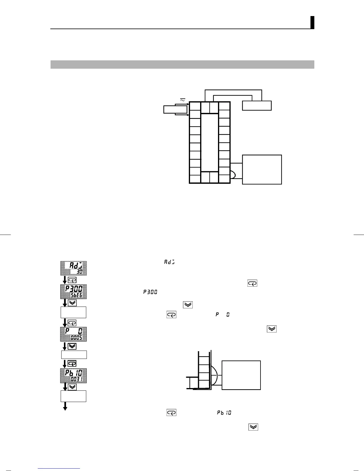
F Preparation
10
9
8
7
6
5
4
3
2
1
20
19
18
17
16
15
14
13
12
11
21 22
23
DMM
6-dial
SOURCE
AC100-240V
(AC/DC24V )
~
• Useleadsofthesamethickness whenconnectingtotheplatinum
resistance thermometer.
• In the above figure, 6-dial refers to a precision resistance box, and
DMM stands for a digital multimeter. However, note that the DMM is
required only when the transfer output function is supported.
• Connect (short) the leads from terminal Nos. 11 and 12.
This example describes how to calibrate a p latinum resistance ther-
mometer when the transfer output function is supported. If the transfer
output function is not supported, skips steps (7) to (10).
(1) When [
] is displayed, the 30 -minute timer is displayed on the
No.2 display and counts down. This timer serves as a guide for the
aging time when agin g is required.
(2) First, calibrate the main input. Press the
key to display
[
] (300Ω calibration display). Set the 6-dial to 300Ω. When the
value on the No.2 display has stabilized (changes of several digits
max.), press the key to temporarily store the calibration data.
(3) Pr ess the
key to switch [ ](0Ω calibration) display. Short
terminal No. 11 to 13. When the value on the No.2 display has sta-
bilized (changes of several digits max.), press the
key to tempo-
rarily store the calibration data.
(4) Next, calibrate the B-B’ input. Change the wiring as follows.
15
14
13
12
11
6-dial
Make the conn ection across terminals 11 and 12 and the 6-dial as
short as possible. Short terminals 11 and 13.
(5) Pr ess the
key to display [ ](10Ω calibration display). Set
the6-dialto10Ω.. When the value on the No.2 display has stabilized
(changes of several digits max.), p ress the
key to temporarily
store the calibration data.
F Calibration
Cont’d on next page
Change wi ring.
Short terminal
Nos.11 to 13
Short terminal
Nos.11 to 13